I'm gearing up to build a somewhat more robust version of my "Miz Piggy" single ended amp using screen-driven 6CD6GA sweep tubes and Hammond 125ESE output iron, set for 5k reflected impedance. This amp is doing duty in my living room, and I've been pretty satisfied with the sound even into so-so speakers. Time for a bigger version....
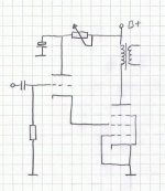
Attached is a schematic of Miz Piggy for reference. The amp is pretty simple, using a 6JC6A video pentode for input gain, and a MOSFET follower stage driving the 6CD6GA output tubes to make sure they get all the screen current their little hearts could desire.
Mr. Piggy will use a similar architecture, but with 6P45S output tube with 500 volts at the plates instead of the 400V used with the missus. For Output iron, I'll be using Transcendar TT-14-OT 8k/10W output iron, with a larger core stack and far more primary inductance than the Hammond iron (for only a little more money, too).
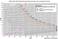
I was thinking of using 12HG7 pentodes for the input stage, but a second look at the Svetlana EL509 curves for screen driven operation leads me to believe I won't be needing all that much voltage to drive the 6P45S screens - that is, if I can believe the Svetlana data. My operating point will be 500V/60-70 mA, which if I believe the curves, will only need around 10V DC bias at the screen, with another 10V or so of drive for full output. This could be accomplished with a much more modest input pentode (6AH6 for example), or even a triode like the 6AB4.
I've noticed that other folks (Danielak, for example) are running the EL509/6P45S in screen driven SE mode with a fairly substantial negative control grid bias. Can anyone comment on the merits of this approach rather than simply pinning the control grid to the cathode? It appears that Danielak wanted to reduce the sensitivity to keep his bias stable and to get away with DC coupling to the driver. I don't mind using a coupling cap, but his remarks about bias stability give me pause.
Attached is a schematic of Miz Piggy for reference. The amp is pretty simple, using a 6JC6A video pentode for input gain, and a MOSFET follower stage driving the 6CD6GA output tubes to make sure they get all the screen current their little hearts could desire.
Mr. Piggy will use a similar architecture, but with 6P45S output tube with 500 volts at the plates instead of the 400V used with the missus. For Output iron, I'll be using Transcendar TT-14-OT 8k/10W output iron, with a larger core stack and far more primary inductance than the Hammond iron (for only a little more money, too).
I was thinking of using 12HG7 pentodes for the input stage, but a second look at the Svetlana EL509 curves for screen driven operation leads me to believe I won't be needing all that much voltage to drive the 6P45S screens - that is, if I can believe the Svetlana data. My operating point will be 500V/60-70 mA, which if I believe the curves, will only need around 10V DC bias at the screen, with another 10V or so of drive for full output. This could be accomplished with a much more modest input pentode (6AH6 for example), or even a triode like the 6AB4.
I've noticed that other folks (Danielak, for example) are running the EL509/6P45S in screen driven SE mode with a fairly substantial negative control grid bias. Can anyone comment on the merits of this approach rather than simply pinning the control grid to the cathode? It appears that Danielak wanted to reduce the sensitivity to keep his bias stable and to get away with DC coupling to the driver. I don't mind using a coupling cap, but his remarks about bias stability give me pause.
Attachments
I´ve built two G2 driven PL519 (40KG6) SE amps based on what I learned from Danielaks article. Both sounded good but both also had problems that were not related to the amp topology itself.
I guess biasing the tubes with the control grids makes the more linear and it definitely decreases the screen grid sensitivity.
With -33V on G1 you´ll need something like 160V static on G2 and some tens of volts for full drive. One benefit is that the whole amp can be direct coupled as long as measures are taken to keep it stable DC-wise.
Will build another amp like this someday, I really liked the sound from G2 driven PL519.
Hi wrenchone,
In such a SD setup, pre-biasing considerably adds to the stability of the operation point. Tim de Paravincini mentioned this during his ETF06 lecture, too, when talking about his own xL509 designs. BTW, the curves Mr. Danielak shows for xL509 SD are not measured ones but extremely idealized modeled ones.
Also on ETF06, I showed how they really look like - measured. Good luck finding a "tunnel" where you can lay your loadline for stable operation ... given you have speakers that are linearized extremely well for most constant impedance over freq.
I never got what is so appealing about xL509 screen drive (or any other tube SD):
- it is very hard to drive due to the Ig2 demand
- it is unstable by design (think Barkhausen, also look up "Dynatron")
- you get rather highish rp for such a tube and all the effort
- you get pretty low efficiency
- THD is quite high (at least compared to xL509 strapped as triode)
Regards,
Tom Schlangen
I've noticed that other folks (Danielak, for example) are running the EL509/6P45S in screen driven SE mode with a fairly substantial negative control grid bias. Can anyone comment on the merits of this approach rather than simply pinning the control grid to the cathode?
In such a SD setup, pre-biasing considerably adds to the stability of the operation point. Tim de Paravincini mentioned this during his ETF06 lecture, too, when talking about his own xL509 designs. BTW, the curves Mr. Danielak shows for xL509 SD are not measured ones but extremely idealized modeled ones.
Also on ETF06, I showed how they really look like - measured. Good luck finding a "tunnel" where you can lay your loadline for stable operation ... given you have speakers that are linearized extremely well for most constant impedance over freq.
I never got what is so appealing about xL509 screen drive (or any other tube SD):
- it is very hard to drive due to the Ig2 demand
- it is unstable by design (think Barkhausen, also look up "Dynatron")
- you get rather highish rp for such a tube and all the effort
- you get pretty low efficiency
- THD is quite high (at least compared to xL509 strapped as triode)
Regards,
Tom Schlangen
Attachments
")
If I don't insist on direct coupling (I most likely won't), a compromise value of negative G1 voltage would probably be ok. It looks like the overall screen sensitivity is not horribly affected, more the static operating point - not a big concern. The tube starts looking more like a 6BQ5 in terms of G2 sensitivity. At any rate, it looks like I'll be lashing a setup together with some bench supplies to plot some curves. I'll be interested to see if I note the same funky behavior documented by Tom. I noticed no weird behavior when I generated curves for the 6CD6GA. Perhaps the setup had something to do with it, as I used a source follower to drive the screen grid. I''ll probably forgo that this time around and just use a bench supply with a small current sense resistor, as I'll only be interested in positive screen bias. With the somewhat G2 decreased sensitivity, the 12HG7 or perhaps a 12BY7 look like viable options for the input stage.
This amp will be as far as I go with a SE screen driven design, as the peak current capability of the sweep tubes is pretty much wasted on an SE design.
This amp will be as far as I go with a SE screen driven design, as the peak current capability of the sweep tubes is pretty much wasted on an SE design.
I never got what is so appealing about xL509 screen drive (or any other tube SD):
I have no experience with the xL509, but I can share some of my other screen drive experiences:
I tried several attempts at SE screen driven amps and didn't find any advantages, and found a few disadvantages. As stated before the drive requirements are high, so is the rP and output impedance. SE implies class A by design and I don't find any advantages to screen drive in class A except the possibility of direct coupling the driver. The efficiency in SE is usually low, but if you want to see an efficient SE (relatively) amp use a triode or triode strapped pentode in A2. I have seen nearly 40% using an E130L "slightly" over its ratings.
I have breadboarded a few P-P screen driven amps. The best one (which will be revisited shortly) used a pair of 6AV5 sweep tubes and made 80 watts without violating the tubes ratings. The plate supply was at 550 volts and sourcing 190 mA. Thats 105 watts in for 80 watts out giving an efficiency of 76%. Distortion at 80 watts was 8%. The tubes were dissipating only 12.5 watts each, no glow in sight.
One thing that you have to watch is G2 dissipation when you drive the amp near clipping with a sine (or worse a square) wave. The plate voltage will be pulled down to near zero on peaks at the same time that the screen voltage is at max. We all Know this is bad for the tube, right? This is not an issue with music, since peaks are infrequent, but I tend to test things at full power for long periods of time!
I also performed some "extreme" screen drive experiments on some cheap sweep tubes that I got during the tube sales that several vendors ran over the summer. There are several screen drive experiments detailed there. In all of my screen drive experiments I used seperate variable power supplies for each element in the tubes under test. This allowed infinite possibilities of the operating parameters. I found that most P-P screen driven designs seemed to work best with a slight negative voltage on G1. This allows G2 to be closer to where it normally runs and seems to lower distortion.
Many of those experiments revealed the limitations of my old Fluke 407D power supply. It is hard to make a 200 watt amp with a 160 watt power supply. I have solved this issue. I now have an old HP power supply that has succesfully MELTED the grid support rod in one of those bad 6BQ6's that I got from AES. It is rated for 600 volts at 1.5 AMPS! It will do about 650 volts at 1.7 amps.
http://www.diyaudio.com/forums/showthread.php?s=&threadid=128533&highlight=
In that thread Wrenchone made this statement:
Maybe your push-pull pcb design in the works can be a screen driven affair using cheap sweep tubes.
I replied:
I am working on a PCB that can be used for high output screen drive, and conventional control grid use too. Unfortunately the two requirements are somewhat conflicting. That is the real reasons for these screen drive experiments.
I am finishing the layout of that PCB right now. It is a hybrid of the original 6AV5 screen drive design, the design used in the AES thread, and the driver from my 300Beast amp. This board can drive 4 output tubes in conventional G1 drive, or 4 in G2 drive, or 2 tubes with drive applied independently to G1 and G2. The DC and AC (drive) voltage can be adjusted independently. There should be enough drive voltage for some cathode follower output stages, but I haven't verified this yet. I am planning another board for those!
It will take a few days to finish the layout, make the PC board, and build the board, but when it is done, there will be some new pictures of glowing tubes. Who knows, I might even make something work.
I may back away from the 6P45S and use an alternate tube with a less touchy screen. I have some 6HF5s (28W) as well as some 6CB5s (23W) from one of my AES buys. I also have a fair number of 6DQ5s (24W) of various flavors, though I'd like to standardize on an output tube with a little bit bigger plate dissipation. Having said that, though, I'm running a pair of GE 6CD6GAs (supposedly 20W) in the missus at 70ma bias with no signs of distress - maybe I don't need to be so choosy. All the above tubes have less sensitive screens than the 6P45S with the control grid nailed to cathode, though still easy to drive with a pentode input stage.
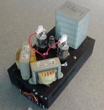
"Miz Piggy" is a fun little amp, and it didn't take too long to get up and running once I finalized a design. "Mr. Piggy is an update with a little more power, prettier chassis, and better output iron. I'm basing the power supply on a massive power transformer gutted out of an old Wurlitzer organ amplifier I picked up on Fleabay.
Attached is a picture of Miz Piggie. The chassis is a little funky, but it cost me nothing. Mr. Piggy will be based on a standard 16" Hammond chassis, giving the tubes and transformers a little more room to breathe
Attachments
I've been staring at Tom's 6P45S screen drive curves, and it looks like the non-linearity sets in when the plate dips below the screen, so that the screens start hogging current. I would venture that by not being so aggressive on the control grid bias, one could considerably push back the point at which this occurs. Since I'm only interested in gaining some bias stability, but not using a DC coupled driver, this seems like an acceptable compromise. This also would probably explain why I noticed no funny business when generating the curves for the 6CD6GA in screen drive mode. I'll start with a grid bias such that the screen sensitivity is similar to other familiar sweep tubes.
I didn't say that I was going to eliminate the negative bias, just reduce it to the point that the 6P45S screen is no more sensitive than the average sweep tube - that's another matter entirely. I'm convinced that you don't need that much negative just for stability if you're not going for DC coupling. Instead of -33V negative bias, say, -5 to -10V, just to pull a number out a place where the sun don't shine. Bench testing will give me a bias I can work with.
Member
Joined 2009
Paid Member
Without negative g1 bias the screen sensitivity must be high so why not steal some ideas from the world of positive bias transmitter tube amps?
This topology is called "Dynamic coupling" and should be self adjusting to a degree:
I like that - clever.
- Status
- This old topic is closed. If you want to reopen this topic, contact a moderator using the "Report Post" button.
- Home
- Amplifiers
- Tubes / Valves
- Initial Thoughts for "Mr. Piggy" SE Amp w/Screen Driven 6P45S