Hello all,
I am interesting in taking a toroid pt that has a 120/120 primary and 12/12 secondary for use in a digital project with at tube buffer. If I connect one primary to the mains and connect the secondaries in parallel, can I use a doubler on the other primary for my B+? I understand that I will only get 1/2 the VA of the transformer, but that is not a problem for me. Any possible issues?
Thanks in avance!
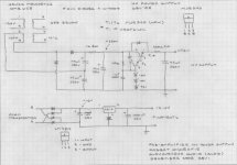
Like this
Audiowize,
Same idea as you plan to use - will likely post in the forum as its own topic as idea develops - using an inexpensive dual primary transformer as mains + filament. I actually have a working prototype using a dirt cheap low profile transformer on my bench powering a 12AX7 phono amp - is very very quiet, high quality and dirt cheap to build
Note that secondary adjacent to the primary you use for the high voltage supply will magnetically couple - meaning you will get more than the 12V out of that secondary so, really can only use one of the secondaries.
Cheers - ALBQ
PS. This ideas is kind of Poindexter inspired - does something similar w/o filament in his Moebius preamp
Attachments
I have seen transformers used in this manner before in several designs published on the web. Anyone contemplating a circuit such as this needs to understand the possible safety issue.
A typical toroid (or conventional) power transformer has both primary windings wound at the same time (often bifilar). The only insulation between each primary winding is the enamel coating on the wire. Then there is a layer of insulating tape (or different bobbin section) between the primaries and the secondaries. This additional insulation is the barrier between the line voltage and the user circuitry in the event that the enamel insulation fails. It is possible, and not unlikely that the enamel will fail if the transformer is overheated or physically abused.
If the transformer is connected as it was intended a short between the two primary windings will cause excessive primary current, resulting in a blown fuse or smoke. Either way the user will know something is wrong.
If the transformer is connected as proposed a short between the two primary windings could result in the users equipment, and any accesories connected to it becoming hot with line voltage resulting in a possible serious shock hazard. This could happen with no indication that anything is wrong. The CD player or turntable could become electrified, while the amp continues to operate.
If this connection is used the chassis, and circuit cround MUST be connected to an earth ground and both sides of the power line supply should be fused. This should be standard practice with any DIY audio equipment anyway.
If you can't verify that the equipment will ALWAYS be connected to a properly grounded electrical outlet, or don't understand the above explanation, don't do this.
Good point, though not all dual-primary transformers are bifilar wound - I have tested a few that took 1500V between primaries without breakdown. I wouldn't use a bifilar-wound primary on 220V - no margin for line surges. If the primaries are wound in separate layers, the DC resistances will be slightly different, as the second one is longer for the same number of turns.
I have taken a few toroids apart and found some that were bifilar and some that weren't. None had any insulation between the two primaries though. All were surplus low cost transformers. They all withstood being tortured as an OPT (lots of voltage), but none worked very well.
I just measured the two Anteks and three Maryland Toroids that happen to be sitting on my work bench and got identical readings on each primary. It is possible that they could be slightly different since the readings were quite low, 2 to 3 ohms. The Maryland units work good as a low impedance P-P OPT.
I also tested an isolation transformer that has 4 seperate 120 volt windings and got 4 distinctly different readings, so this one clearly has 4 seperate windings. I haven't tried to take one of these apart yet. They have an epoxy filled center, which has prevented me from winding a additional secondary and trying it as a P-P OPT.
I have used some of them as filament transformers a while back, but don't have any around currently. I don't know any way to tell for sure how they are consructed without taking one apart, and those are not coming apart without a fight!
If you are using it yourself and are sure that everything is properly connected and grounded, you are probably OK. I posted my reply just to be sure that the user understands the possibilities. I have seen too many people that cut the ground prong off of everything in the name of hum reduction, and there are places (like my mother in laws house) that still have two prong wall outlets. Using a circuit like this in a situation like that is an invitation to a disaster.
If you are using it yourself and are sure that everything is properly connected and grounded, you are probably OK. I posted my reply just to be sure that the user understands the possibilities. I have seen too many people that cut the ground prong off of everything in the name of hum reduction, and there are places (like my mother in laws house) that still have two prong wall outlets. Using a circuit like this in a situation like that is an invitation to a disaster.
"high pot" (I don't know what that means)
it is a test method whereby a test voltage of say 500vdc is impressed upon the two windings for a period of say 1 minute.
the meter is set to read in megohms, the ideal of course is an open circuit,however, since there is capacitance between windings, there will be an initial low reading and it goes up with time....
highpot fails if the readings are going down with time instead of going up...
i do a lot of high pot testing of cables up to 45kV in my line work....

- Status
- This old topic is closed. If you want to reopen this topic, contact a moderator using the "Report Post" button.
- Home
- Amplifiers
- Tubes / Valves
- Toroid PT question