Dear Friends,
I have been wondering why compensation mechanisims are not frequently used in tube voltage amplification stages. Contrastly, I have seen the following methods being applied in solid state amps:
1. Miller compensation (known as Lag comp??)
2. Phase lead compensation ( used by JLH and others)
3. Combination of the above to tame over the top reactive load.
4. 2-pole compensation (well documented by D. Self)
5. PILL compensation scheme..
Now the question is why don't we see these in tube amps? Is it the case that tube amps don't suffer from instability issue?
Could someone shed light on this matter?
Happy Holiday!
-Atiq
I've moved this over to "Tubes."
In any case, tube amps have been built with all sorts of feedback schemes. Certainly because of the presence of the output transformer, the feedback tends to be much lower (20dB is a lot in this world!), so not as many tricks need be played to keep things stable. But compensation and the equivalent of Miller compensation are quite standard. There are also quite a few schemes (such as cathode feedback around the output stage) peculiar to tubes that are not seen in transistor amps. Different devices, different topologies, so unsurprisingly, different means of lowering distortion and output impedance while keeping things stable.
In any case, tube amps have been built with all sorts of feedback schemes. Certainly because of the presence of the output transformer, the feedback tends to be much lower (20dB is a lot in this world!), so not as many tricks need be played to keep things stable. But compensation and the equivalent of Miller compensation are quite standard. There are also quite a few schemes (such as cathode feedback around the output stage) peculiar to tubes that are not seen in transistor amps. Different devices, different topologies, so unsurprisingly, different means of lowering distortion and output impedance while keeping things stable.
Thanks SY, I was thinking of moving the post but u did it.
Correct me if I am wrong but the compensation techniques native to ss amps are also used in tube amps. However, out put x-former somehow limits nfb so does typical compensation scheme. Also triodes got its own inherent feedback properties..
I sarted this question with a hybrid amplifier in my mind where a buffer satge like the following one, developed by Steve Dunlop, driven by a tube front end:
http://www.diyaudio.com/forums/showthread.php?s=&threadid=134619&perpage=25&pagenumber=1
What sort of compensation do you recommend in this hybrid? Lets assume it is driven by Broskie Aikido front end with 5751 tubes for gain.
Going back to original question, how compensation is realised in this modified ultrapath amp where output is connected with a transformer:
http://www.tubecad.com/2008/08/blog0147.htm
Cheers
Atiq
p.s: how do u attach image?
I fixed your links.
Re JB's Ultrapath, no compensation is needed because there's no feedback loop. This is usually the case with SETs, since the idea of the amp is not to have a linear path from input to output, but rather to "beautify" the sound. The distortion figures and source impedance bear testimony to my admittedly cynical observation.
Re JB's Ultrapath, no compensation is needed because there's no feedback loop. This is usually the case with SETs, since the idea of the amp is not to have a linear path from input to output, but rather to "beautify" the sound. The distortion figures and source impedance bear testimony to my admittedly cynical observation.
Ok.
I got it in simple terms,
'no gnfb calls for no mandatory frequency compensation'
but without gnfb, I am open to higher distortion (desirable SET sound by many listener) and uncontolled ouput impedence (???) or damping factor ...
Therefore, If I wish to drive steve dunlop's non-switching class-B solid state buffer with an Aikido tube amp, I wouldn't worry about lead/lag or 2-pole compensation.
Now what happens when a gnfb loop or error correction loop (as in Pax amp by Jan Didden, utilise AD844 CCII for MJ Hawksford principle) is put on across steve dunlop's non-switching class-B buffer, while driven by a non feedback tube gain stage ? Do we care about compensation for VAS stage?
Many thanks for your patience.
I know the Pax circuit, I meant the other buffer you mentioned. In either case, the tube block will not have a lot of gain. It will generally be run as an independent unit, with the loop running around the solid state block. IOW, you run the tube circuit open loop (it's pretty linear that way and has appropriate gain), then set the ec to give unity gain for the solid state block that the tube stage is driving. Compensation goes inside the ss block, it's not needed in the tube stage.
here is a strip down version of CCII HEc loop:
http://www.diyaudio.com/forums/attachment.php?s=&postid=1477253&stamp=1207509381
Note that pin X, Y, Z of AD844 form basic HEc loop which could be applied across instead of any traditional gnfb loop. Now the question is: is there any benefit of this loop over traditional gnfb loop. I can understand the availability of ready-made Current conveyer ad844..
Later..
apologies, SY.
here is Mr Dunlop's non-switching (?) SS buffer:
http://www.diyaudio.com/forums/attachment.php?s=&postid=1681435&stamp=1228947106
cheers
here is Mr Dunlop's non-switching (?) SS buffer:
http://www.diyaudio.com/forums/attachment.php?s=&postid=1681435&stamp=1228947106
cheers
some thought on non switching ss buffer driven by Aikido
For some reason, there has been little information available on non-switching class-AB SS output stage to DIYers.This is likely to be commercial arena.....
However, there is no harm in exploring it more during this festive time..
True Non Switching Class AB?
Here is an interesting patent, no. 5057790 –‘ High efficiency class A amplifier’ by Ernest Landi, which I like most for Aikido font end driving. Whilist there are few patents available for non switching class AB , this one stands out by realising all active devices in either non saturating or non switching state .
A brief from of the patent:
An object of the invention is to greatly reduce the crossover distortion inherent in prior art Class AB amplifiers. This is accomplished by including in an amplifier (such as a modified Class AB amplifier) means for preventing either of the output transistors from being cutoff during any portion of a waveform. This result is achieved without any other transistors in the circuit being cutoff or saturated during any portion of a waveform. All transistors are operated in their linear active regions at all times. As is known, any deviation from a linear transfer function causes distortion. In general but not universally, a gradual or smooth non-linearity is more desirable than a sharp or discontinuous non-linearity because it is less objectionable to hear and is easier to minimize with feedback. Therefore, advantageously there are no sharp discontinuities associated with any internal transfer functions of the circuit in accordance with the invention.
The patent can be fetched from:
http://patent2pdf.com/
just type in the number 5057790.
This amplifier utilise output device in emitter follower configuration and get assistance from non linear current mirror sub circuit preventing output transistor from going into cut off.This stops cross over dist., which is thought to be culprit for nasty & unwanted higher order harmonics...
Here is a good explanation on non-switching output stage from our forum friend Steven:
http://www.diyaudio.com/forums/showthread.php?threadid=36728
In a class A amplifier normally a current increase in one output transistor goes together with an (almost) equal decrease of current in the other.
In a class AB amplifier normally an increase in current through one output transistor (with approx the bias current) makes the other transistor non-conducting.
In a non-switching cass AB amplifier an increase in current through one output transistor lowers the current in the other transistor in a non-linear way and such that it will not go to zero. The advantage is that this transistor will not be reversed biased (as will happen in normal class AB) and this makes switching on again much faster.
There is a complete circuitry with some indicative device details (fig 5) in the afermentioned patent. Disregard the wrong sign notation in driver transistor.
Here is another good read on non switching stage from professor Hawksford .This can be downloaded from:
http://www.essex.ac.uk/DCES/research/audio_lab/malcolmspubdocs/C82 Non-switching amplifier.pdf[/URL]
He proposes combining the non switching output stage with error correction loop.
Now the question is which one will be sonically superior?
Later..
atiq19 said:How do you insert images?
Atiq
If you want to attach images, just use the attach file function below the reply box, and browse to them on your computer. I believe they need to be less than 100 KB in size.
If you want the image directly in your post, you need to put your images on a web page and point your post to the images using the
Boywonder,
I will try that now. Already tried before but did not work. I noticed some erratic behaviour since I installed IE7 latest security patch.
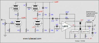
Here is an image I wanted to post Re post 9 by SY:
The schematic courtesy Tubecad Journal.
A tube front end driving SS buffer (LM12), the tube stage is pen loop whilist SS buffer has its own fb mechanism.
Cheers
I will try that now. Already tried before but did not work. I noticed some erratic behaviour since I installed IE7 latest security patch.
Here is an image I wanted to post Re post 9 by SY:
The schematic courtesy Tubecad Journal.
A tube front end driving SS buffer (LM12), the tube stage is pen loop whilist SS buffer has its own fb mechanism.
Cheers
Attachments
5751 tube
Does anyone have any experience in using 5751 tube? I am planning using this tube in my Aikido tube amp driving SS buffer.
http://www.nickdangerous.com/misc/mghead/
It looks like someone already spent much time with this tube.
How subtle is the difference between Sylvania made 5751 vs others as claimed in the above page? Any idea?
I need to find some UK supplier for 5751 with reasonable price during this recession ...
Mostly over-wrought. There certainly are variations in the distortion spectra, but you'll get just as much (if not more) variation by slightly adjusting operating points. As it happens, the JJ which he slagged tends to have very good THD and harmonic distribution if loaded properly.
There are other tubes which should work just as well, if not better, as voltage amplifiers if the 5751 proves difficult to find. My first choice would be a 6SL7/6SU7/5691. For the follower tube, you want something with a much higher gm. A classic choice is the ECC88 and variants.
There are other tubes which should work just as well, if not better, as voltage amplifiers if the 5751 proves difficult to find. My first choice would be a 6SL7/6SU7/5691. For the follower tube, you want something with a much higher gm. A classic choice is the ECC88 and variants.
rudîmentum
SY,
I am not sure whether you prefer this acronym to address you?!
Let me know if it is otherwise.
Why follower tube in Aikido topology has to be higher gm?
As I understood, Aikido topology is sensitive to tube mismatch, top and and bottom tube in a twin triode...
As there any way around it?
Can you elaborate on operating point adjustment? How could it be arranged in practice?
Thanks for your comments on 5751 myth..
Call me anything you like. 
A high gm tube will have a low output impedance, so it's better for the follower; the output Z is about 1/gm. The operating point is set by the cathode resistors. If you have a means of measuring the distortion spectrum, you can adjust them for the best looking result.
A high gm tube will have a low output impedance, so it's better for the follower; the output Z is about 1/gm. The operating point is set by the cathode resistors. If you have a means of measuring the distortion spectrum, you can adjust them for the best looking result.
- Status
- This old topic is closed. If you want to reopen this topic, contact a moderator using the "Report Post" button.
- Home
- Amplifiers
- Tubes / Valves
- Tube Amp Compensation Q