Miles - your help in here!
I recently took delivery of an octet of 807s. All are NOS JAN RCA. Enough acronyms.
I have lusted after a mid-output tube amp for a while. I've built a trio of 12ax7/EL84 SE units, a 6j5 buffer, and a 6CM5 SE spud. I'm now overconfident and recognisably underskilled.
Did I mention I intend to wind the OPTs myself?
OK, so here are the issues for me. I greatly admire Miles' 807pp design and understand the concepts if not the detail of the schematic. However, my leaning is toward some thing a little less complex - preferably three stages. I'm thinking a pentode preamp, cathodyne triode splitter/driver to the 807 outputs.
Source is entirely digital - no vinyl to have to equalise.
I have a clutch of 6j5 triodes, 6sj7 pentodes, a mix of the usual console-derived novals. THe EL36's don't belong in this project, but if I let you know I have a few, who knows what may be suggested - voltage regulator pass tubes perhaps?
Think monoblocks folks, and separate power supplies to each.
Music is bass heavy, a mix of rocks, dance/house, punk, moving toward blues jazz and light opera. OK, so I'm eclectic.
I figure AB is a given and looking for around 35W - the spec sheet says 500V anode, 300V screens, -27V grid, 8k a-a load.
SUggestions? Sanity Checks? Christmas greetings?
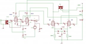
Consider building something along the lines of this.
The positive rail can be derived from a valve full wave rectifier, the negative rail can be derived from a silicon full wave rectifier. Both rails can come off the same 320-0-320V transformer.
Expect output to be in the region of 25W of class A Pentode output. This will sound better than almost anything else you could build. The design is a simplification of Gary Pimms Tabor amplifier.
The only serious issue to face is that the CCS's under the outputs can see in excess of 300V over them, which requires a special kind of design. I used TV deflection transistors configured with a darlington driver - consider this a single darlington pair, this is then configured as a ring of two with a high hfe transistor in control. Once I worked this out they have presented no issues over many on off cycles.
Shoog
Attachments
As a side-note on 'simpler' 807 PP designs, what would Shoog or anyone else for that matter think of this circuit: http://tinpan.fortunecity.com/saints/668/primer/807-pp.gif
To a beginner like myself it looks charming in it's simplicity, uses some rarely seen feedback methods... and at last provides a way to make use of all those Hammond opt secondaries")
Cheers - Simon
PS I see the link doesn't work; googling fi primer 807 should get you there
To a beginner like myself it looks charming in it's simplicity, uses some rarely seen feedback methods... and at last provides a way to make use of all those Hammond opt secondaries
Cheers - Simon
PS I see the link doesn't work; googling fi primer 807 should get you there
hi and thanks shoog
I had left the transformer-splitter option off my list but had been considering it. It seems to give a number of advantages, not the least being it splits the signal at the very front end and leaves the active units to amplify and drive - the things they do best. I'm not interested in inter-stage transformer splitters - I just can't justify the iron to get the required bandwidth....
I had left the transformer-splitter option off my list but had been considering it. It seems to give a number of advantages, not the least being it splits the signal at the very front end and leaves the active units to amplify and drive - the things they do best. I'm not interested in inter-stage transformer splitters - I just can't justify the iron to get the required bandwidth....
In my design I use a mains toroidal at the front end to do the splitting. In order to preserve bandwidth it is essential to step down the signal. Since the 6AU6 has plenty of gain, I use a 4:1+1. This is a nice cheap option that has worked well with no issues to speak of.
Shoog
Shoog
Klimon said:As a side-note on 'simpler' 807 PP designs, what would Shoog or anyone else for that matter think of this circuit: http://tinpan.fortunecity.com/saints/668/primer/807-pp.gif
In a word: YUCK!.
In the first place, a 6SL7 doesn't have the moxie to properly drive the grids of an 807. Though not exactly a difficult load, the grid circuit has more Cgk + Cmiller + Cstray than a 6SL7 can handle. The 6SL7 was intended for useage as a high gain small signal triode. As such, it has eeeeeeeeeeeeeenormous static and dynamic plate resistances. It'll work at sub-milliamp plate currents. This making possible the use of huge plate loads without requiring insane rail voltages. What the 6SL7 likes to see is a Hi-Z, Lo-C load, and an 807 ain't it. Furthermore, when the finals clip, the 6SL7 will simply roll over and die. Even before clipping, you're gonna have a slew problem at the high end. Fixed bias and RC coupling is bad news. An overdrive transient that turns on the GK parasitic diode will accumulate an additional negative voltage at the grid (how RF amps and oscillators derive most, if not all, of their operating bias). That will put the finals into a more nonlinear part of the plate characteristic. Even if you don't hear an actual clip, you will notice the resulting sonic degradation.
Secondly, a triode IS NOT a constant current source. If you're going to use an LTP/Schmidt/differential phase splitter, you need a CCS in the tail. That means a small signal pentode, or better still, cascoded BJTs.
If you're gonna go to the expense and bother of building your own, then build something worth your time and effort. This PoS isn't it.
If you want "simple" than go with Shoog's design. 6AU6s look pretty good so far as linearity goes. Looks like he's got a good Q-Point. Since it's a differential, that'll improve the THD situation. The active tail loads on the 807s will mean no Class AB, crank it to 11, but you can live without those extra few watts.
The only suggestions I would make is to stiffen up that screen supply with a voltage divider instead of a series dropping resistor, and adding the LR plate stoppers. 807s tend to want to make RF.
Thanks for the excellent analysis Miles, Many things I missed.
With regard to stiffening the 807 screen, after consulting with Gary Pimm on it, I dropped the screen filtering altogether. This is because with a smoothed screen supply the amp tends to hum more as it amplifies the supply ripple at the plates. I use minimal supply filtering overall (8uf 5H choke and then 50uf). I reference the screens to the raw +B. As we have discussed before the plate to plate feedback linearises everything a treat and I have an almost hum free amp to boot. Output impedance is sub triode strapped.
Also on the screen supplies to the 6AU6 the pot has been replaced with two 10K resistor, one for each screen. Again gary advised that this would lower distortion by introducing a bit of degradation. In the Tabor original Gary uses the pot to balance current in the finals. I deliberately wanted to avoid that and that is why I put the CCS's in the tails of each of the 807's so that they wouldn't drift at all. I am certain there is a slight sonic penalty, but sufficiently small to be outweighed by the advantage of not having the chore of bias balancing. This is critical in my design because I have used 120+120V : 6V mains toroidals as outputs. These can tolerate no more than a couple of milliamps of imbalance. Response is good down to 20hz and present to 10hz.
Shoog
What for parasitics
Hi;
Some pointers to watch for with the 807. Circuit design stability is essential with the 807 as technically its an RF tube which can be used for Audio - just like some Audio tubes can be used for RF ( note the 6V6 in one such case ).
I have had a lot of experience over the years with 807 tubes in amplification equipment and I have to say I have a lot of respect for them - when set up correctly.
One issue to watch for is parasitic oscillation that may creep in due to poor component layout,. grounding issues, of incorrect impedance matching.
If such does become an issue, place a 47 ohm resistor ( I have seen a 100 ohm used as well but no higher) in series with the plate ( right at the plate cap end and not at the transformer end ) of the anode line for each 807 in the circuit. Wind over the top of the resistor with enameled copper wire, about 22 gauge will be ok - its not critical.
Wind the resistor full from end to end ( on the old Phillips 1 watt carbon resistors I used which were about 20 mm long and 5 mm dia they formed the coil former for the coil ). You ended up with about 20 turns in all. If you don't have a resistor use a blown glass fuse of the same dimensions such as a 3AG with the innards removed and fit the 47 ohm inside the glass tube. Solder the coil to each end of the resistor or fuse caps. Seal the coil when wound and soldered with varnish or epoxy glue. Cover it with heat shrink or some other suitable high voltage insulation.
This component forms a Radio Frequency choke in parrallel with the 47 ohm. This is known as a parrasitic plate stopper. Rarely used nowdays, but common in the Tube RF circuits.
In some cases, GRID stoppers where also needed and for audio applications a series 1k ohm resistor was placed right at the input control grid terminal on the 807 socket after the coupling capacitor and grid bypass resistor.
Parasitics can cause red anodes killing the output tube(s), output transformers to fail on one side of the output stage ( often open circuit) and spurious distortion, not to mention radio interference and a crappy sound performance and in some cases even fire in the amplifier - as I observed years ago when a 300 watt Phillips PA amp went up in flames at the output transformer.
An oscilloscope is the best way to monitor these parasitics as a distinct RF signal sits on the side of the sine-wave under test.
If you driving class AB2 or class B 807s will need low impedance drive from a transformer or a cathode driven driver stage, such as a 12AU7. As much as many don't want to hear it negative feedback assists in suppressing parasitic Oscillations. Screen suppression with a bypass capacitor can be useful at times. Values ranging from 1-10 nf will often do the trick, soldered right at the screen of the tube socket to the nearest ground point at the cathode.
Cheers
@Shoog:
Miles opiniated exclamation prompted me to take a closer look at your circuit and it doesn't look so complex as the tabor lineage might suggest. Also I have two LL1527 1:1+1. A few questions:
-- Do you have a schematic of the CCS you use on the 807s
-- Regarding PSRR: high for the output stage / in the league of classical anode follower driver for the 6au6's?
-- What value 6au6 screen stoppers are you using?
Simon
I lashed up my CCS from components I salvaged from old monitors. If you were serious about going ahead I would draw a schematic from what I have done.
I would say that the PSRR was better than an anode following. By keeping the amp tightly differential from front to back it surpress's power supply noise by cancellation. Gary Pimm said that he could get power supply filtering down to about 20uf but that transient response eventually suffered. I have a very slight buzzing coming from my speakers, but this is not power supply noise - its something else and not significant enough to be worth tracking down. My speakers are very sensitive so its a good result.
The pot has been eliminated and the screens have 10K on each pin.
Looks like the LL1527 would do a treat in the front end.
Shoog
Yep, I actually intend to build the circuit (iron and tubes at hand so they WILL be put to use, and things fall in to place for me with this schemo)... which due to ongoing projects doesn't mean that it'll happen in the next few months. I'm sure others would equally benefit from a schematic of the CCS
All else being quite clear, for the design of the B- supply I'ld be much helped if you can point out what the current draw of the driver stage is and how sensitive it is to ripple (i.e. in the ballpark of an anode follower driver B+ or perhaps the minimal requirements for this amps B+ are no different for this supply?).
Thanks for your time --- much appreciated!
Simon
Its a while since I built this, and unfortunately I had a major system crash which wiped out most of my records. Still the 6AU6 LTP draws about 11mA of current and then the VR150 takes about 17mA to bias it up. I used one VR150 for both sides (not a good idea as it introduces cross talk). Given this information it should be relativly easy to lash up a negative supply and then to adjust it to exactly the right spec. My negative supply fits on a small circuit board about 4inchs square. I used ultrafast soft recovery diodes, snubbed with caps. I then fed that into a 100R resistor to emulate the behaviour of a vacume rectifier. I then had a CLC filter using a little salvaged inductor. Works very well.
I will have to take a look at exactly what I did with the CCS, its very simple but a very exacting design. i tried about four different circuits before I got something reliable. This is because on switch on nearly all the 350V of pos supply is over the cathode which pushes almost all transistors outside their safe operating area.
Shoog
- Status
- This old topic is closed. If you want to reopen this topic, contact a moderator using the "Report Post" button.
- Home
- Amplifiers
- Tubes / Valves
- 807pp suggestions and guidance please