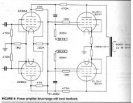
I like to try this design (see picture, comes from Glass Audio). The question is what splitter will perform good at the front of it. I need some gain because my tweaked cd-player has a weak signal (less than 2 volts). I am not good at tube theory so I need something I can copy easily.
I like to use the ecc40 (is like a e80cc) but other options are also possible (ef86, 12hg7, 5842, 6c45, 6h30, 2c51, 76, 6n1p, 6n6p, D3a, etc.).
I am thinking about transformer splitting (I have a cinemag) and then a differential stage. Or perhaps a LTP with ccs under it or a tube followed by a concertina splitter. Any suggestions or suitable designs that fit before this:
Attachments
It takes a very good (read expensive) transformer to perform step up duties. This is because they are intriniscally high capacitance items. Fortunately an input transformer is about the easiest position to drive so you may get away with a 1:1+1 input transformer.
A CCS LTP driver stage, driven from only one input can only ever achieve half the Mu of the input valve. However you could put a transformer infront and drive both inputs of the LTP and so achieve the whole Mu of the triode.
Another thing to consider is creating a Pentode LTP at the front which would give you massive gain.
Unfortunately you really need to work back from your anticipated output power to the front end and establish how much gain you actually need. You may be surprised that you might need very little and all options are open to you.
Shoog
I think Shoog is right about not needing much more gain, and I suspect that an LTP splitter, using your ECC40 with CCS in the tail, would do the job well.
The CCS could be made up of a couple of PNP transistors in cascode but you'll need a negative supply for that. However, since you'll need a negative bias supply for the OP tubes anyway, maybe it can serve both purposes.
The CCS could be made up of a couple of PNP transistors in cascode but you'll need a negative supply for that. However, since you'll need a negative bias supply for the OP tubes anyway, maybe it can serve both purposes.
Boris_The_Blade said:Driving those 6CB6s should be really easy. Why not just use a simple pentode (or triode) driving a cathodyne splitter? ...especially since this is a learning exercise as well. This should have better bandwidth (and distortion if done right) than any transformer too.
The reason not to use a cathodyne phase spliter is it has asymmetrical output impedance. The phase taken from the cathode has a much lower output impedance than the phase at the plate. Under load, the higher impedance plate phase losses gain which results in asymmetrical drive voltages to the output tube grids. The LTP splitter is the better way to go.
Rgs, JLH
JLH said:
The reason not to use a cathodyne phase spliter is it has asymmetrical output impedance. The phase taken from the cathode has a much lower output impedance than the phase at the plate. Under load, the higher impedance plate phase losses gain which results in asymmetrical drive voltages to the output tube grids. The LTP splitter is the better way to go.
This is a canard that has been exploded over and over. If the cathodyne is loaded symmetrically (as would be the case here), the frequency and phase response at both outputs will be identical. The apparent source resistance at both outputs will be identical and low.
Jaap said:
I am thinking about transformer splitting (I have a cinemag) and then a differential stage. Or perhaps a LTP with ccs under it or a tube followed by a concertina splitter.
I am using a differential amplifier by a pair of Hi-gm of C3g. The
schematic is seen in my Web below.
http://ja1cty.servehttp.com/6080/60802.html
Because of Hi-gm, a pair of C3g can drive -70V biased 6AS7 to
the full swing where the input voltage is less than 1V.
As you can see, it resembles to yours but the cathodes are
connected and pulled down to -160V via 22Kohm as is intended
to be a quasi CCS. If you will use transistor CCS with about
-15V, -160V is not necessary. -15V can be obtained by
AC 6.3V and voltage doubler rectifying.
If your will use Hi-gm pentode such as C3g, D3a, E180F, 12HG7
and E280F, enough voltage gain will be obtained to drive EL34
without input transformer splitter.
Here are a couple of ideas that might work.
Vixen Main Schemo
Le Renard Main Schemo
Both use variations on the LTP splitter. The 6SL7 based splitter (Vixen) has a gain of 25.
The cascoded LTP in Le Renard has a gain factor of 40, which was more than enough open loop gain so that it is the sole gain stage in that design. 6BQ7s, though not considered an audio type, still sound just great.
Think about the 6au6 pentode in a LTP. masses of gain. A simple single transistor screen supply would do nicely and can be shared between the pair for better regulation. It has the best current capability of any of the small signal pentodes, easily delivering 5mA or more.
Shoog
Shoog
SY said:
This is a canard that has been exploded over and over. If the cathodyne is loaded symmetrically (as would be the case here), the frequency and phase response at both outputs will be identical. The apparent source resistance at both outputs will be identical and low.
From everything I know, you are incorrect. It is impossible for the cathode driven phase to have the same output impedance as the plate phase.
Let’s take a text book example. We have a cathodyne splitter consisting of a 6SN7 with 18K plate and cathode resistors. The B+ supply is 330V and the tube current is 5mA. Therefore, there is 90V across each 18K resistor and 150V across the tube. At this operating point the Rp is 9.1K, Mu is 20.1 and Gm is 2.2mA/V.
The output impedance of an anode follower is Rp in parallel with the plate resistor. So 9.1K//18K = 6044 ohms.
The cathode impedance of a cathode follower is Rp/(1+Mu). The output impedance would be the cathode impedance in parallel with the cathode resistor.
First the cathode impedance is 9.1K/(1+20.1) = 431.3 ohms. Now for the output impedance. 431.3 ohms//18K = 421.2 ohms.
I really don’t know how you can claim that 6044 ohms is equal to 421.2 ohms. The cathodyne phase splitter most certainly does NOT have symmetrical output impedance to each of its phases.
Rgs, JLH
You've neglected the feedback. Draw the equivalent circuit incorporating the (symmetrical) AC loads. It may become clearer that since the plate current and the cathode current are equal, the drops across the loads are equal. That's independent of frequency, so one can just as easily say that the source impedances when the loads are symmetrical are also symmetrical. If the loads are not equal, then indeed the source impedances become unbalanced.
There's a very nice mathematical derivation of this slightly surprising result in Morgan Jones's book, "Valve Amplifiers," 3rd edition.
There's a very nice mathematical derivation of this slightly surprising result in Morgan Jones's book, "Valve Amplifiers," 3rd edition.
Much higher than that !JLH said:
. . .
Let’s take a text book example. We have a cathodyne splitter consisting of a 6SN7 with 18K plate and cathode resistors. The B+ supply is 330V and the tube current is 5mA. Therefore, there is 90V across each 18K resistor and 150V across the tube. At this operating point the Rp is 9.1K, Mu is 20.1 and Gm is 2.2mA/V.
The output impedance of an anode follower is Rp in parallel with the plate resistor. So 9.1K//18K = 6044 ohms.
Effective tube Rp is to be multiplied by (almost) Rk x Mu and you must add Rk
Here is the feedback !
Now that Rk is introduced in the calculation of the internal impedance of the anode branch, check what happens when both Ra AND Rk are changed by the same amount . . .
Yves.
I second Sy to the fact that when loaded symmetricly the concertina has very low (and equal) Zout on both outputs. And I think we can consider the load symmetrical! One mustn´t forget the feedback involved.
Did an example with 12AX7 a while ago and as far as I remember Zout was a few kohms on both sides! EDIT: Rechecked and Zout was in the ballpark of 600ohm/side with phase and response being equal!
This can easily be showed using a simulation program.
About the driver circuit a LTP with a 6N30P or a 6SN7 should do a good job. As they both have Ug in the ballpark of 5V at the currents to be used, no negative voltage will be needed for the CCS.
Though I think the gain will be a little, high due to CD having the very high nominal output level of 2V.
Did a check on JLHs example and it showed Zout just below 400ohm/side.
Unequal capacitances might disturb things a little as there where a phase-difference of 2 degrees at 1Mhz when loaded by 400ohms") !
!
The outputs aren´t totally equal with normal loading of 100k though, as capacitances might play a greater part. So in this case a ca 8p cap between cahode and ground equalizes the outputs to be identical up to 1Mhz .
Unequal capacitances might disturb things a little as there where a phase-difference of 2 degrees at 1Mhz when loaded by 400ohms
! The outputs aren´t totally equal with normal loading of 100k though, as capacitances might play a greater part. So in this case a ca 8p cap between cahode and ground equalizes the outputs to be identical up to 1Mhz .
The outputs aren´t totally equal with normal loading of 100k though, as capacitances might play a greater part.
There's only a 1-2pF difference in Cgk and Cgp, so a gimmick could take care of the 2 degree phase shift at 1MHz, if that's causing neurosis.
- Status
- This old topic is closed. If you want to reopen this topic, contact a moderator using the "Report Post" button.
- Home
- Amplifiers
- Tubes / Valves
- What splitter for this design ?