Hi Folks,
There's a lot of good information up here on pentodes vs. triodes, but I'm still trying to wrap my head around some of the numbers involved. I'm building the simple preamp circuit depicted below, and thinking about substituting a pentode (likely a 5879 or 12AU6 or such) for the 12AX7 in the first position:
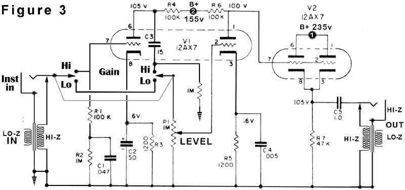
Aside from getting the pinout and voltage right (that's another can of worms for sure), what are the ramifications of this switch in terms of input / output impedance or other technical (rather than aesthetic) concerns?
Many thanks,
Seth
There's a lot of good information up here on pentodes vs. triodes, but I'm still trying to wrap my head around some of the numbers involved. I'm building the simple preamp circuit depicted below, and thinking about substituting a pentode (likely a 5879 or 12AU6 or such) for the 12AX7 in the first position:
Aside from getting the pinout and voltage right (that's another can of worms for sure), what are the ramifications of this switch in terms of input / output impedance or other technical (rather than aesthetic) concerns?
Many thanks,
Seth
slor said:Hi Folks,
There's a lot of good information up here on pentodes vs. triodes, but I'm still trying to wrap my head around some of the numbers involved. I'm building the simple preamp circuit depicted below, and thinking about substituting a pentode (likely a 5879 or 12AU6 or such) for the 12AX7 in the first position:
Aside from getting the pinout and voltage right (that's another can of worms for sure), what are the ramifications of this switch in terms of input / output impedance or other technical (rather than aesthetic) concerns?
Many thanks,
Seth
You should get better linearity with the pentode.
Personally I prefer a triode for my guitar as the none linearity of
the 12AX7 gives a warmer tone.
A whoile generation of rock was built up on none linear valve guitar amps !
You shouldn't have any major impedance issues. Although the output impedance of a pentode is equal to its anode resistor, that's not massively greater that the output impedance of the existing triode, and it's feeding a 1M pot, which is sufficiently high in value as to make little difference.slor said:
Aside from getting the pinout and voltage right (that's another can of worms for sure), what are the ramifications of this switch in terms of input / output impedance or other technical (rather than aesthetic) concerns?
Many thanks,
Seth
If you intend to use one of the "traditional" pentode arrangements, with 220k anode resistor, you'll probably find the pentode is a lot more sensitive than the 12AX7 (easier to overdrive with the guitar alone), giving less linearity, not more. However, such high-gain arrangements are prone to microphonics. I would recommend 100k on the anode, at most, with an appropriate screen resistor (470k to 1M?).
A pentode/triode switch is a useful addition too.
Oh, and be sure your tranny can handle the heater current.
EDIT: I see your HT is low, so I would definately NOT recommend anything greater than 100k on the anode, to avoid microphonics and over-sensitivity.
Thanks much for the info, this is just the sort of stuff I was looking for! Some of the concepts are a little beyond me at the moment, but I'm confident I can at least enact the work and then study the results.
Speaking of which, I haven't really given much thought to the screen grid yet. Is there a formula or ratio for the screen grid resistor vs. the anode resistor? (I know the screen should see less HT than the anode, but how much less?)
That brings up the question of HT in the first place: As I'm building the power supply from scratch, I can give the plate any amount of voltage, within limits. I understand the concept of the power band (and of course I have a tube manual) but is there a "typical" value for both the anode and screen? (I already am planning to sit down and study some schematics, but thought it was worth asking for the technical background....).
Again, many thanks!
-Seth
slor said:(and of course I have a tube manual) but is there a "typical" value for both the anode and screen?
Again, many thanks!
-Seth [/B]
My data sheets on valves/tubes gives working voltages against required resistors. Its just a matter of choosing a voltage and taking teh resistor values from the table.
slor said:Speaking of which, I haven't really given much thought to the screen grid yet. Is there a formula or ratio for the screen grid resistor vs. the anode resistor? (I know the screen should see less HT than the anode, but how much less?)
Unforch, there isn't. Hollow state isn't like solid state. In a transistor, everything is connected together so that definite relationships exist, and you can always figure AC and DC design by formula. A VT has all its internals just hanging there in free space, all doing their own thing. Therefore, you need the plate characteristics, and for pents, the forward characteristics (there should be at least two: plate current vs. grid voltage at various screen voltages, and screen current vs. grid voltage at various screen voltages, and it also helps to have a g(m) plot as well).
As for screen voltage: as low as you can make it, consistant with gain and output swing for the best linearity. The screen supply should be stiffened (since the current demand isn't great, those little neon panel lights make good regulators, but only if the cathode is at AC ground) with a heavily bled voltage divider if it's necessary to bypass the screen to the cathode if the voltage at the cathode varies either due to the use of cathode degeneration or using it as a gNFB summing node. If that's not done, and the cathode voltage varies, you get an Ultralinear type operation with lower than anticipated gain.
I wouldn't use a single series dropping resistor for screen voltage as this will turn any pentode into a variable-u type and in all likelyhood ruin the sonic performance.
That brings up the question of HT in the first place: As I'm building the power supply from scratch, I can give the plate any amount of voltage, within limits. I understand the concept of the power band (and of course I have a tube manual) but is there a "typical" value for both the anode and screen? (I already am planning to sit down and study some schematics, but thought it was worth asking for the technical background....).
Again, many thanks!
-Seth
If you're using an audio final, the spec sheet should give you some Q-Points and THD specs. Otherwise, draw up some loadlines.
since the current demand isn't great, those little neon panel lights make good regulators,
Are you refering to VR tubes or something else? If something else, where can one get these neon lights?
Jeb-D. said:Are you refering to VR tubes or something else? If something else, where can one get these neon lights?
Not VR tubes, but those small neon glow tubes that are often used as indicator lights. These are about an inch in length with no sockets, just the plain wires. They have designations like NE-2, NE-45, etc. They work like VR tubes, but at much less current (a few mA) and have DC striking voltages of 90 -- 135Vdc.
Ahhh.. These guys.
http://en.wikipedia.org/wiki/Neon_lamp
Looks very interesting for use as a g2 regulator. Have you found their noise performance acceptable?
http://en.wikipedia.org/wiki/Neon_lamp
Looks very interesting for use as a g2 regulator. Have you found their noise performance acceptable?
Jeb-D. said:
Are you refering to VR tubes or something else? If something else, where can one get these neon lights?
Something else I use intensively:
http://www.alldatasheet.com/datasheet-pdf/pdf/183129/EPCOS/SIOV-S10K17.html
More stable and less noisy than a zener or neon bulbs.
Large choice of value.
Yves.
No one has mentioned pentode partition noise which is one of the reasons why you don't see a lot of guitar amplifier front ends using them. (Like lots of "tube rush" type noise??) Passive guitar pickups can have relatively low output (tens to hundreds of mV) depending on their design and need quiet, if not entirely linear gain in the following stage.
Incidentally the 12AX7 is generally quite linear as a plain voltage amplifier, and more so than most commonly used audio pentodes, it really all depends on the chosen operating point.
I would build that design as shown.
Incidentally the 12AX7 is generally quite linear as a plain voltage amplifier, and more so than most commonly used audio pentodes, it really all depends on the chosen operating point.
I would build that design as shown.
I would suggest this as a starting point: http://www.freewebs.com/valvewizard/pentode.htmlslor said:Speaking of which, I haven't really given much thought to the screen grid yet. Is there a formula or ratio for the screen grid resistor vs. the anode resistor? (I know the screen should see less HT than the anode, but how much less?)
Sort of, the datasheet will normally give a collection of 'recommended' values and working voltages. I woudl recommend you DON'T aim for the one with the highest gain, since it will exacerbate microphonics, which is a real pain in a guitar amp.I understand the concept of the power band (and of course I have a tube manual) but is there a "typical" value for both the anode and screen?
Also, I fear your thread may get lost in a sea of hifi related replies. For a guitar amp, you certainly DON'T need a regulated screen voltage. Part of the appeal of pentodes for guitar is the natural compression introduced by the screen, so a single series resistor is the preferred method. A pot, wired as a variable resistor, in series with the screen decoupling cap makes a powerful 'compression' control too.
kevinkr said:No one has mentioned pentode partition noise which is one of the reasons why you don't see a lot of guitar amplifier front ends using them. (Like lots of "tube rush" type noise??) Passive guitar pickups can have relatively low output (tens to hundreds of mV) depending on their design and need quiet, if not entirely linear gain in the following stage.
I do believe that the issue of partition noise is exaggerated. Pentodes, and even pentagrid converters (more screens and even more partition noise) have long been used for the front ends of BCB and SW xcvrs. The signal coming off the antenna is an order or two of magnitude below the output of a pickup (uV's not mV's). It's not until you get below 40M that you have to start worrying about it.
I didn't know we were discussing gee-tah accessories here, so disregard all previous posts. That's a whole 'nother story from doing Hi-Fi design.
Miles Prower said:
I do believe that the issue of partition noise is exaggerated. Pentodes, and even pentagrid converters (more screens and even more partition noise) have long been used for the front ends of BCB and SW xcvrs. The signal coming off the antenna is an order or two of magnitude below the output of a pickup (uV's not mV's). It's not until you get below 40M that you have to start worrying about it.
I didn't know we were discussing gee-tah accessories here, so disregard all previous posts. That's a whole 'nother story from doing Hi-Fi design.
You may be right, but an snr of just 10dB is considered usable from an RF perspective, whereas a similar snr in audio is useful only in the context of the minimum required snr for a valid FFT based measurement. I have not looked at the spectral content of partition noise, but I understand partition noise has a 1/f type of noise distribution, ie falling with rising frequency so should not be much of a concern at low RF frequencies. At higher frequencies cascode and triode RF amplifier topologies are common..
I have certainly heard pentode based phono stages which from a noise perspective were fairly unacceptable. (And ones that were ok) (Leak and a few others)
Something else I use intensively:
SIOV-S10K17 datasheet pdf datenblatt - EPCOS - Leaded Varistors ::: ALLDATASHEET :::
More stable and less noisy than a zener or neon bulbs.
Large choice of value.
Yves.
Just had to revive this thread
")
But how do you use those? I see them on your PS schematics, but how did you determine the voltage drop across them? Measurement?
- Status
- This old topic is closed. If you want to reopen this topic, contact a moderator using the "Report Post" button.
- Home
- Amplifiers
- Tubes / Valves
- Substituting Pentode for Triode