Having purchased this driver board for one of my Dynaco Stereo 70's and found it less than optimal I am wondering if I can change the input tube to a 6SL7. I am still in the learning process of working with tubes and do not know the pits and downfalls of trying such a feat. I do not know how to figure the optimim operating point the usage of the tube load lines and calculation of the cathode resistors.
Attachments
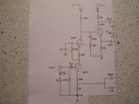
Ray is correct about that being a kind of cascode. What about that circuit's performance is objectionable? Have you tried "rolling" 6SN7s?
Given that you are dealing with a PCB, topology changes are a PITA. AFAIK, you will not find an Octal small signal twin triode with higher gm than the 6SN7 already in situ. A small rearrangement to "conventional" voltage divider bias of the upper triode and a LED stack for lower triode bias might be feasible, but I don't know if you will get an improvement in performance.
Given that you are dealing with a PCB, topology changes are a PITA. AFAIK, you will not find an Octal small signal twin triode with higher gm than the 6SN7 already in situ. A small rearrangement to "conventional" voltage divider bias of the upper triode and a LED stack for lower triode bias might be feasible, but I don't know if you will get an improvement in performance.
It doesn't sound anywhere close to the Mapletree Stereo 70 driver board I have in another Dynaco amp. It just sounds lifeless and has a lack of low end punch that I enjoy in the Mapletree board. I have rolled a number of 6SN7's in it with very little difference. The Chrome top Sylvanias seem to be about the best all around tube for it. It seems to lack the luster that I feel the 6SL7 seems to have. Its just plain bland
It doesn't sound anywhere close to the Mapletree Stereo 70 driver board I have in another Dynaco amp.
Can you post the Mapletree schematic? If you like the Mapletree PCB so much, why did you switch?
Along the lines that Ray indicated previously, you could try a higher gm twin triode in the cascode. If you build Noval socket to Octal plug adapters, you could try the ECC99. Be sure to wire the grid connections with 1 KOhm Carbon comp. stoppers, not plain wire. High gm types, like the ECC99, are quite vulnerable to parasitic oscillation. The ECC99 data sheet is here.
Eli,
Its got a copyright but you can download the manual at
http://hollowstate.netfirms.com/
I bought the board because I thought it might sound good.
Its got a copyright but you can download the manual at
http://hollowstate.netfirms.com/
I bought the board because I thought it might sound good.
OK, the Mapletree PCB uses Mullard style circuitry, with a 6SJ7 as the pentode voltage amplifier and a 6SL7 as the LTP phase splitter. Lloyd Peppard is very much an octalist and (given his orientation) the mapping over of the Noval EF86/12AX7 is not unreasonable. Please observe that the 6SL7 is not the I/P device.
If you want to "monkey" with the 3 tube board, using ECC99s in the cascode L/R voltage gain blocks (as previously suggested) could work out well. A 6SN7 section serving as a "concertina" phase splitter is quite reasonable.
Protecting O/P trafo cores against saturation is a matter of routine for me in circuits containing GNFB loops. I'd add PIO caps. at the I/Ps, which combine with the 470 KOhm grid leak resistors to "corner" in the 17 - 19 Hz. range. Having purchased core saturation insurance, advantage of the greater gain available from ECC99 cascodes can be taken to increase the low (2.54) NFB %. That should improve the "punchiness" in the bass region. Hafler designed Dyna O/P trafos for use with significant amounts of NFB. The fellow who designed the 3X 6SN7 driver board is (IMO) not more clever than the late Dynaco founder.
Thanks Eli,
I will give up on the 6SN7 board and put it back on the shelf.
I have been playing with a CCS on the LTP 6SL7 on Lloyds board.
I don't quite understand his copyright on this design however
because both the Mullard input stage and the long tail pair have
been used in other designs. Maybe it is possible to copyright a
method of construction as his is different with the three fibreglass
and turret terminal parts mounted component boards. Anyway I
have been playing with his design and have made some changes
which I believe have contributed to the sonics of the design.
One can't copyright a design or a construction method- the copyright is on the drawing. If you redraw it and post it, there's no copyright violation.
As we discussed by email, it's possible to do a 6SL7 conversion to the first stage by dumping the cascode idea, but it won't be optimal. You need a lot more gain in that first hole to make the feedback effective, and the DC biasing can be a bit tricky.
If I were to do a cascode up front, it would have a moderately high transconductance FET on the bottom. With a FET having 5mA/V of gm and a 100k plate resistor on the upper tube, the first stage gain would be 500. To knock that down to the required stage gain of 30 or so, you'd have room for 24dB of feedback. This could be distributed by using a local feedback scheme through the output tube cathodes (a la Audio Research) and the remainder as a global feedback loop; doing the whole thing with global feedback would be a real stability challenge, but I think there's a lot of merit to using a combination of local and global. Likewise, you could drop the plate resistor to 50k for a stage gain of 250, and just use the standard global feedback loop.
SY,
The ECC99's gm is 9.5 mA./V. Not much in the way of net ZL is needed to get a stage gain of 250X from that tube in cascode. A quick look at the ECC99 data sheet suggests that a 2X red LED stack for bottom triode bias will provide for a very reasonable set of operating conditions.
The ECC99's gm is 9.5 mA./V. Not much in the way of net ZL is needed to get a stage gain of 250X from that tube in cascode. A quick look at the ECC99 data sheet suggests that a 2X red LED stack for bottom triode bias will provide for a very reasonable set of operating conditions.
- Status
- This old topic is closed. If you want to reopen this topic, contact a moderator using the "Report Post" button.
- Home
- Amplifiers
- Tubes / Valves
- Can I change the input to a 6SL7?