Hi There,
I have my faithfull GU50 pp amp for a few years now, allways adressing different parts and improving things. They sound good right now, biassed at 74 mA
Now I have set my eye to the right point for biassing the tubes. I have allways seen them as close to kt88 and biassed them accordingly.
Is there a way to measure the right bias point? I know you can find the bias point for a guitar amp with a scope, but can you empirically determine the bias point for a hifi amp too? so far my searches have been unsuccesfull.
It is in penthode mode. UL and triode are to be tried yet. I know my OPT's are lowish, somewhere like 3K, but I don't know how to measure that truthfully and the curves I found for GU50 are not the curves I found I needed to calculate bias..
Hi
To me it seems that ideal biasing should aim at lowest possible distortion. That will require quite some iterations on the actual curves of the GU50's. One also needs to know the exact operating points, including the B+, the voltage at the screens and the load. I have seen GU50 curves for screens at 250V and at 150V.
About the output transformer: have you tried to calculate the voltage ratio of primary to secondary? That value squared multiplied with the load on the secondary will give the primary impedance. But I am sure you knew that...
Erik
hi erik,
due to my recnt movin to a difernt place my "lab" is very limited. I was hoping there would be a trick to measure sometning with a scope or something.
I had an encounter with the half wave rectified end of the amp some times ago. I am a bit shaken about it and need some time to find the courage to get to the HV section again.
My B+ is 445 V, screens at 250, regulated by ecl82's
The curves out there for GU50's are scarce, incomplete and they are said to be not very representative due to differences in manufacturers.
I am capable of doing math, but am a bit overwhelmed and inconfident sometimes, hence my question fo an empirical method...
It produces sound with great authority now, so i Guess I am not that far off...
Still I'd like to optimize.
The OPT's are from BEARD P100 amps, using 4x KT88. I am concidering using 4x GU50/channnel to match the OPT's or going triode...
You aren't far off. Biassing hard usually reduces thd as output stage is forced into flatter class A with better o/p transformer damping. So the HF sine performance usually coincides with lowest thd which sounds sharper. Nearly all tube amps have a dismal thd record at 10KHz even at 1/2 power of a few %,
So on harder quiescent setting the 10KHz square wave will have a better rise/fall profile all important to the definition. This is why older EL34 amps sounded so dull.
The alignment is emperical; My example; I have two monster double parallel p-p UL amps; one has 6550's and the other KT88 Svets. Although o/p trannies are different, quies biassing per tube sits optimally vs.thd at 85mA at 450V B+ and 60mA at 530V for KT88's; this stuff is getting hot...studying this more carefully, the lowest thd results at 10KHz when o/p stage is forced into class A'ish, so full load current is a modest 110mA.
Beware of conflicts; the AC output stage drive must also be symmetrically balanced, i.e the o/p stage tubes have sim gm. This is a mighty awkward way of doing things but what else is there ?
Loudspeakers aren't resistors and the output stages see different. A good tube vendor will check this for you and give you a gm/v per anode current figure at a specified voltage. If your amp runs at 400V then specify checks at this voltage.
If one wants top performance in fixed bias; also make sure the power supply can take the extra current without flopping on transients. ( a common form of intermodulation thd). Also make sure of adequate ventilation.
Older Class AB amps i.e set quies at a cold 50mA which usually equates to 130mA as o/p stage goes into class B on transients; can give a shrill distorted top end audio response when encountering digital replay material.
If one is contemplating a new design from scratch, then one can carefully optimise parameters.
Good listening !
richj
Thanks for that reply. interesting reading, but I am confused to the usefulness.
I have about 150 GU50's bought in bulk. No fancy overcharging vendor to be seen.
These are GOOD GU50's else I wouldn't have bought them. There are a lot worse out there. Same batch numbers perform usually within 2% of eachother.
If I bias at higher currents (90-100 mA), the plates start to mildly glow, so I don't want to go there....
Hi
Parallel Push Pull with GU50's in triode sounds as an interesting project! But your question wasn't about that, so I won't bother...
About the glow: one member here, Wavebourn (sure he will pop up) described that the GU50's keep working fine even when dull red. Seems that the plate material can take that...still I do not know if it shortens the tubes life...
May I know ask you two questions about your amps?
- are you running some form of feedback?
- are you still using the original Soviet sockets as in your avatar? I have four and it is really hard to put the GU50's in and out. Have you found some trick to facilitate this operation?
Now let's wait until Wavebourn (Anatoliy) pops up!
Erik
beamnet said:Is there a way to measure the right bias point? I know you can find the bias point for a guitar amp with a scope, but can you empirically determine the bias point for a hifi amp too? so far my searches have been unsuccesfull.
The idea that you can find an "optimum" bias point with an o'scope is nonsense. That has caused a lot of problems. By one interpretation, you severely underbias, and by another, overbias. The best idea is to bias as close to Class A as you can get, consistant with the final's Pd rating. Otherwise, there really isn't any "optimum" as with solid state since the transistion from Class A to Class B is considerably slower with VTs than it is with transistors.
If your working Pd is 70% -- 80% of the rated Pd(max) then you don't have anywhere else to go. I did a project where I could increase the Pd considerably higher than Pd(max) and get a decided sonic improvement, but those finals were 6BQ6GTBs -- a TV horizontal deflection type that was rated very conservatively (consistant with the demanding service: max RMS power output for hours a day for years at a time -- even then HD finals were the first VTs to go in TV's) and so didn't red plate at Pd= 18.5W despite the Pd(max)= 12W. You won't get away with that with audio finals.
The bucket style sockets are awesomeness. The heftiest sockets of all in my opion. Most people think they are ugly, I think they rock!
There are two ways of getting them out better. If they are "audiophile" is up to the reader:
-Lubricate them! Using graphite or copper fat. Mak shure not to short the pins out.
-Gold plate the pins or add a thin layer of solder to them. They are very rough the pins making for hard removal. smoothing them out helps. Lead is a fairly good "lubricant".
I tried both, but now I just pull them out by force. I made a noose from a small piece of rope and tied it to a handle.
There are sockets with high quality turned contacts. mayb ethese are better...
If you want to part from those four sockets drop me a line!
beamnet said:
If I bias at higher currents (90-100 mA), the plates start to mildly glow, so I don't want to go there....
The only option is to faithfully listen and settle the electric bill.
Studying a 1950's preamble on the KT66 and KT88, quotes "red hot anode is normal" . There are lots of NOS running cherry hot which have stewed for 10K hrs or more. As to shortening tube life; that despends on how good the materials are.
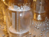
I'm strongly suspecting the Tung Sol New Edit 6550 isn't made with properly outgassed materials. The getter opposite the anodes has a markedly paler grey boundary after 500 hrs use. pic encl. Proper getter functioning yes, but shortcuts on material quality. Neverless, still an excellent and stable performer. Comments welcome.
richj
Attachments
Thanks for the information on the sockets. I also had to use a lever to extract the GU50's from the socket. I wanted to test the rest of a batch I had bought, but never did it due to fear of messing to much with the valves and eventually breaking them...
Great info on the feedback! I have open baffle speaker and have been reading for a while on the benefits of a transconductance amplifier to feed them. Pentodes without feedback seemed to be the ideal solution, but I was scared off by the comments about odd harmonics and the like produced by pentodes...now I know that at least you have had good succes with feedbackless GU50 in pentode. Thanks!
About the sockets... I will not sell them due to this project above that one day should be accomphished.
Sorry that I can't be of more help to your original question, but thanks for the several answers yoy gave throughout the thread.
I'm strongly suspecting the Tung Sol New Edit 6550 isn't made with properly outgassed materials.
Do the svets seem to last a long time?
The name is Bas, the alias is from a long time ago when I used to maintain www.geocities.com/beamnet
- Status
- This old topic is closed. If you want to reopen this topic, contact a moderator using the "Report Post" button.
- Home
- Amplifiers
- Tubes / Valves
- Finding bias point in PP fixed bias