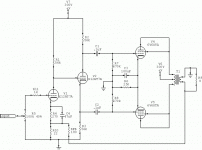
So, this is my second time to post something. I have built this small 6V6 push pull amplifier out of some spare parts. I have included my schematic of the amplifier section. This includes some numbers and values. Just fyi I dont know much about the output transformer, I stole it off a Bogen Amplifier that had a pentode power tube and triode in the same glass tube El86 or something? At any rate I beleive it to be rated from 6-10K Ohms on the primary, it also has a 70volt line isolated secondary tap. That aside;
First: I would like to add a feedback loop which I have not done yet; i would like suggestions.
Second: Also I would like to see some math for the feedback if someone could do so?
Thirdly: I have indicated in red a grid stopper resistor, is there a reasonable value for what I have drawn? Also being as there should theoreticaly be no input current I coud pick this to be 100K as well?
Lastly: Any suggestions on the circuit would be much appriciated.
Any information or suggestions would be much appriciated. Thanks again,
Jonathan
As above. Except I'd use the ECC40 which is a terrific sounding tube, very popular in European equipment. Three stages of 12AU7 is out to lunch and then some.
Actually I'd use a 1J6G as driver. Just discovered this little jewel of a double DHT and can't get enough of it - have it in my linestage. You'd need a preamp since mu is about 15. And a DC filament supply since it's directly heated, but that's simple enough and the tube is cheap.
andy
Actually I'd use a 1J6G as driver. Just discovered this little jewel of a double DHT and can't get enough of it - have it in my linestage. You'd need a preamp since mu is about 15. And a DC filament supply since it's directly heated, but that's simple enough and the tube is cheap.
andy
jerluwoo said:Your circuit will not work.
I dissagree, I have it built currently and it operates. It could be debated how well it works but that aside it works.
Thanks for the input that it is overly complicated, now that I step back it does look a little excessive all for just a little output. A simpler solution could be had. I will take a look at a simpler circuit.
Again to repeat however, if I wanted to put a global feedback network is there some mathmatical solution to go about this? Local feedback I somewhat understand; however, once I need to take the tansformer into account I get a bit lost. Do I just make a voltage divider based on what I expect at one of the secondary taps? Then just assume that voltage divider to feed back an overall % compared to the input?
I mainly agree with those above; the main problem with your circuit is that it has way too much front end gain, so the noise level will be a little higher than optimum. You could remove that third front end stage and drive directly off the split load inverter, it would improve the sound, I bet.
If your outputs are operating in triode, as shown, I think it would be a mistake to apply global feedback around the circuit. You would probably be disappointed in the reduction of space, image, and inner resolution. Feedback was used in the pentode amps of the Bogen period because the output impedance of the amp would be unacceptably high without it, thus the inclusion of extra gain stages to supply Av that would be subsequently lost in the NFB.
If you wish to try NFB, take a wire from the top tap of the output transformer secondary, through a resistor of about 15K - 18K (try different values experimentally), but not to the top of that 10K cathode resistor; you gonna put that voltage on your output secondary winding. Split that resistor into 8.2K on top and 1.8K on the bottom, and attach the NFB loop to the junction.
This will give you 6-8dB of NFB to listen to, and not send the amp into oscillation.
Spearmint on!
Poinz
I say that it doesnt work because of your phase splitter. As it is the tube is biased well into cutoff. Since you have the grid referenced to ground then you have that 56k resistor from cathode to ground biasing the tube. It would work like that if you were using a negative voltage supply, but not as is. Also the input tube is biased very close to cuttoff as well. It should only need a cathode resistor of 560 to 620 at most with the 100k plate resistor. Take some voltage measurements at the plate of the input tube and the cathode of the phase splitter tube and you'll see what i mean.
")
J_Hart_14 said:So, this is my second time to post something. I have built this small 6V6 push pull amplifier out of some spare parts. I have included my schematic of the amplifier section. This includes some numbers and values. Just fyi I dont know much about the output transformer, I stole it off a Bogen Amplifier that had a pentode power tube and triode in the same glass tube El86 or something? At any rate I beleive it to be rated from 6-10K Ohms on the primary, it also has a 70volt line isolated secondary tap.
Before you do anything else, I'd look for a better OPT. A 70V secondary obviously implies PA use, and sonic performance wasn't part of that design. That right there will be a significant improvement, seeing that you trioded the 6V6s. Trioded 6V6 amps often run open loop, but that takes some decent OPT iron.
First: I would like to add a feedback loop which I have not done yet; i would like suggestions.
I'd say FUGEDDABOUDIT. With three RC couplings (two of whose turn-overs fall almost right on top of one another) plus an inferior OPT that'll go squirrelly at the low end as well as the high end, phase stability under gNFB is going to be highly questionable. In my designs as well as such classics as the Williamson (which this resembles) we try to get away from RC coupling as much as possible, favoring DC coupling, such as between the input stage and the cathodyne. If a second RC coupling is needed, its turn-over should be removed from the other by a decade for phase stability.
Second: Also I would like to see some math for the feedback if someone could do so?
1 + BAvol= Avol/Avcl
Avol: Open loop gain
Avcl: Closed loop gain
B: Gain of the feedback network
Solve for B
Thirdly: I have indicated in red a grid stopper resistor, is there a reasonable value for what I have drawn? Also being as there should theoreticaly be no input current I coud pick this to be 100K as well?
A reasonable value is probably in 4K7 territory. 100K would be way too big. Don't forget that the grid stopper interacts with the VT's Ci + Cmiller + Cstray to form a LPF. With 100K, you'd lose all your highs.
Lastly: Any suggestions on the circuit would be much appriciated.
Redesign that front end to DC couple to the cathodyne, make that third gain stage a true differential by adding a common tail resistor to preserve the AC balance of the cathodyne.
mach1 said:Unecessarily complex. You can drive a 6V6pp with a single 12AT7 long tailed pair. Type in 'el cheapo' and do a search of the forum. Also do a search under 'musical machine' for a slightly different approach.
What he said (just to emphasize the point)
We have an el cheapo with EL84 tha really is very good (it looks like yours would if the 1st 2 stages were eliminated, a CCS on the LTP, and a bit other juggling). Poinz's Music Machine is also reputed to be quite outstanding (i'll be getting a chance to hear a local build this month)
dave
So, I found this website to help me design the LTP section.
http://www.freewebs.com/valvewizard/acltp.html
So what I have done is updated my schematic and added another page to give operating values and a visual reference for what should happen.
Thanks again for all the input, and again any comments on the new schematic are welcome. I believe this is what was suggested for the circuit modification.
Jonathan
Attachments
^^^^
That's better, however, it can be further improved by using an active tail load and a negative rail. That way, you can run the grids at DC ground, and the active tail load will greatly improve the AC balance, so that you won't have to force it with unequal plate loads.
Here are a couple of examples of that: Le Renard Main Schemo
For this design, the LTP is a cascode of 6BQ7A's. The CCS in the tail runs off a negative rail, and so the grids are at DC ground. It's convenient for the purpose of getting another DC blocking capacitor out of there at the gNFB summing node.
Vixen Main Schemo
Since the LTP is the second stage; it was NBD to DC couple to the grids, and run the tail CCS at a positive voltage above DC ground as there was sufficient Vpp at the positive rail to spare.
In both cases, the CCS is cascoded BJTs, as this both improves the impedance and reduces the tendency for high frequency AC to flow around the CCS, thus defeating the purpose. BJTs make good CCS's since this device has much higher gain than the usual pentode hollow state CCS.
- Status
- This old topic is closed. If you want to reopen this topic, contact a moderator using the "Report Post" button.
- Home
- Amplifiers
- Tubes / Valves
- 6V6 Push Pull