EDN Magazine has an article: "Get More Power with a Boosted Triode" in the April 3, 2003 edition. Here's a link:
http://www.e-insite.net/ednmag/inde...rticleId=CA286250&pubdate=04/03/2003&text=6l6
http://www.e-insite.net/ednmag/inde...rticleId=CA286250&pubdate=04/03/2003&text=6l6
Attachments
Honestly,I wouldn't dare to try it in real-life use,especially if I had to use some highly-priced 6L6's.
If you really intend to give it a try,use some 5881's ,at least for the beginning.
I can recomend you the Russian version of 5881 (namely 6Pi3S-E,the ones without a base collar).These are able to withstand incredible dynamic conditions of use (and abuse),conditions never dreamed about average 6L6.Not even the original (metallic) ones.
Regards,
EDN Publishes corrections
they published some corrections to their April article. Here's the link:
http://www.e-insite.net/ednmag/inde...02240&pubdate=6/12/2003&spacedesc=designideas
they published some corrections to their April article. Here's the link:
http://www.e-insite.net/ednmag/inde...02240&pubdate=6/12/2003&spacedesc=designideas
> Makes sense to me but screen current ought to go way up.
Right; though I am not sure it goes "way up". In a simple Tetrode, G2 higher than Plate will soar the current. In Pentodes or Beam Power tubes, the G2 current soar does not happen until Plate sinks very low, 50V-100V for typical designs, around the knee of the plate curves. For Sine, and especially speech/music, we usually spend so little time at low plate voltage that G2 survives the peak current and power.
But Screen Current is one place you should NOT rely on SPICE models.
#1: the SPICE tube models usually do not model ordinary pentode screen current accurately (and say so in the fine print). In almost all normal curcuits, you don't need to know the screen current with any precision.
#2: screen current is one of the few "free variables" open to a tube factory. They have to hold several dimensions to high precision. G1 location must be very precise or designers and users will complain. But G2 location is less important, so they allow a little leeway so they don't have to work so hard and charge so much.
#3: the "Beam" design with G1 and G2 aligned, made famous by 6L6, is VERY fussy. If they are perfectly aligned, primary G2 current goes to zero over most operating conditions. Including secondary current, the G2 current in a 6L6 is often negative at some operating conditions. (I have seen negative G2 current at 400V plate and G2 and 50mA bias.) But they are never perfectly aligned, and many recent-production tubes are pretty sloppy. If just a few of the G2 wires sit "between" G1 wires, screen current soars. OTOH if G2 is good but they use a soft plate metal, secondary emission soars and the G2 current goes more negative at idle.
Also the simulated values exceed the G2 voltage ratings on most 6L6-type bottles. (Yes, you can exceed the book values on the better class of 6L6 and get satisfactory life for guitar and hi-fi duty.)
Further: in general, this plan needs a floating power supply for "every" 6L6 (or bank of simple-parallel 6L6). One for a mono SE amp, two for push-pull (which is what the 6L6 specifically was designed for!), four for stereo push-pull. (However you can grow to 2x200W with 16 6L6 in push-pull parallel and still use just four supplies.)
And each supply should have semi-decent regulation, since G2 voltage sets bias just as much as G1 voltage. And that supply current may be small, large, or negative, depending on plate conditions and tube replacement. At the present price of a basic 6L6, it is almost as cheap (and a lot better looking) to parallel a second 6L6 than to buy another transformer winding, rect-cap, and load regulation resistor (to absorb any negative current).
Also: there is nothing new under the sun. This is an old hack. It makes a little sense if you need to drive a high current low impedance load and don't have transistors. Set the 6L6 Plate at 100V, keep the Screen up around 250V, you can get large current without exceeding the plate dissipation rating. The customary connection was to take output at the Cathode and bypass G2 to Cathode. Since the optimum design for this kind of abuse holds the 6L6 at semi-constant voltage drop, that does about the same thing as their trick of referencing G2 to the Plate. Not quite, but not radically different.
PRR said:...Also: there is nothing new under the sun. This is an old hack.
Quite. I love how these magazines and desginers feature "new" techniques that are lifted from old WE schematics, and RCA patents. If the technology were current, instead of anachronistic, these guys would be in legal hotwater - as opposed to just looking slightly silly.
A certain "ultrapath" connection comes to mind...

"ultrapath"
Hi Joel.
Lets call names")
I have no idea what jack told you but...
Jack told me that he had "rediscovered" an old W.E. circuit and was calling it "ultrapath" to best describe in his own words what it did when he used it in his designs. I have never heard him once say that he came up with the idea. As a matter of fact I have heard him and others give W.E. engineers a LOT of credit for their work in the past

Regards
Andrew
Hi Joel.
Lets call names
I have no idea what jack told you but...
Jack told me that he had "rediscovered" an old W.E. circuit and was calling it "ultrapath" to best describe in his own words what it did when he used it in his designs. I have never heard him once say that he came up with the idea. As a matter of fact I have heard him and others give W.E. engineers a LOT of credit for their work in the past
Regards
Andrew
- Status
- This old topic is closed. If you want to reopen this topic, contact a moderator using the "Report Post" button.
- Home
- Amplifiers
- Tubes / Valves
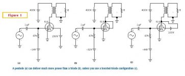
- 6L6 Design in EDN Mag