For the benefit of some members who want to see or may not be quite sure on how to proceed, I'm going to post a running commentary, with pix, on constructing the simple 2A3 design from Gabevee. I will post pix's and explanations through my different step's and answer questions to clarify how or why to anyone interested. Hopefully this gives the new guys some idea as to how this is done from scratch. Possibly it may give some old hands a new trick or two, maybe even me.") I will post the first part this weekend.
I will post the first part this weekend.
I will post the first part this weekend.First Pix
Here is the first of many:
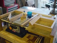
In the first pix we see a couple of chassis being built. It is easier to buy a metal chassis from Hammond. I spend about 20.00 on oak and a lot of time cutting and assembling and finishing, but I like the look. The choice is yours, and a Hammond chassis is a perfectly viable alternative (not everyone has a table saw in his garage). Anywho, The sides are 7/8ths oak with a 1/4 inch slat glued to it. I use the 1/4 inch piece to provide a shelf for the top plate to sit on. I sandwich these two pieces between the aluminum plates with clamps while the glue dries to insure uniformity and a tight joint between the two. I then cut the 45's on each end, and the shelfs for the top and bottom plates. Using the heavy aluminum plates and a square, I then glue each side to each other to form the perfect square. I use the top plate during this procedure to insure good fit and squareness. Once this box is done I then add corner bracing using wood cut from the 1 1/2 x 1 1/2 inch wood block. I run this down the table saw to cut two triangular pieces, and cut the triangular pieces to fit in the corners of the wooden box. This serves two purposes, 1) to rienforce the frame and, 2) to provide an anchor point for the top and bottom plate. Everything is glued together using tite bond wood glue. This whole process takes me two to three days as the joints must dry at least an hour before they can be carefully handled. I always glue one at a time to ensure a perfect fit. Questions?
Here is the first of many:
In the first pix we see a couple of chassis being built. It is easier to buy a metal chassis from Hammond. I spend about 20.00 on oak and a lot of time cutting and assembling and finishing, but I like the look. The choice is yours, and a Hammond chassis is a perfectly viable alternative (not everyone has a table saw in his garage). Anywho, The sides are 7/8ths oak with a 1/4 inch slat glued to it. I use the 1/4 inch piece to provide a shelf for the top plate to sit on. I sandwich these two pieces between the aluminum plates with clamps while the glue dries to insure uniformity and a tight joint between the two. I then cut the 45's on each end, and the shelfs for the top and bottom plates. Using the heavy aluminum plates and a square, I then glue each side to each other to form the perfect square. I use the top plate during this procedure to insure good fit and squareness. Once this box is done I then add corner bracing using wood cut from the 1 1/2 x 1 1/2 inch wood block. I run this down the table saw to cut two triangular pieces, and cut the triangular pieces to fit in the corners of the wooden box. This serves two purposes, 1) to rienforce the frame and, 2) to provide an anchor point for the top and bottom plate. Everything is glued together using tite bond wood glue. This whole process takes me two to three days as the joints must dry at least an hour before they can be carefully handled. I always glue one at a time to ensure a perfect fit. Questions?
Attachments
Parts and Layout
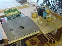
Next up is iron. Here we see my choice of transformers and chokes. This is a quicky here so nothing exotic, Hammond 272JX for power, 125ESE's for output and a 193S choke. This will be my first listen to SE Triode so if I like it I will pop for the 1627's. Anyhow, in the pic we see my layout of parts about how I want them. Notice the power transformer turned 90' degrees from the output transformer. This keeps it from inducing interference into the output transformer. Proper layout is something you should think about. Transformers get hot, tubes get hot, wiring must be considered. This will become obvious the deeper I get into this multipart series so I will not go off on a tangent now. For now, this is the layout I have chosen. You will notice the top plate to the left of my layout and it already has holes in it. The use of a square, tape measure, and sharp marking utensil is of huge benefit here. You can see my marks transfered to the plate and pilot holes were drilled on a drill press. I start with a small 1/8th's bit and drill all holes. I then move up to larger bits drilling each hole and dropping off of each hole as it gets to the size it needs to be. Some thought about bolts and such is necessary beforehand. I use the sizes 6/32 , 8/32, and 10/24. The first number is bolt thickness and the second is threads per inch. The large holes were punched out with the tools in the green case above the plate. These are greenlee knock out punches and create a very clean and perfectly round hole. They use a bolt to draw a cutter through the metal into a backing cup. You can see the cutters sitting in their cups in the kit. You have to have a hole first to put the bolt through but they work great. They are around 90.00 for the kit but if you have a friend who is an electrician he should have a set you might borrow. I am taking care of the big parts now and will decide what lugs I need to allow for later on.
Next up is iron. Here we see my choice of transformers and chokes. This is a quicky here so nothing exotic, Hammond 272JX for power, 125ESE's for output and a 193S choke. This will be my first listen to SE Triode so if I like it I will pop for the 1627's. Anyhow, in the pic we see my layout of parts about how I want them. Notice the power transformer turned 90' degrees from the output transformer. This keeps it from inducing interference into the output transformer. Proper layout is something you should think about. Transformers get hot, tubes get hot, wiring must be considered. This will become obvious the deeper I get into this multipart series so I will not go off on a tangent now. For now, this is the layout I have chosen. You will notice the top plate to the left of my layout and it already has holes in it. The use of a square, tape measure, and sharp marking utensil is of huge benefit here. You can see my marks transfered to the plate and pilot holes were drilled on a drill press. I start with a small 1/8th's bit and drill all holes. I then move up to larger bits drilling each hole and dropping off of each hole as it gets to the size it needs to be. Some thought about bolts and such is necessary beforehand. I use the sizes 6/32 , 8/32, and 10/24. The first number is bolt thickness and the second is threads per inch. The large holes were punched out with the tools in the green case above the plate. These are greenlee knock out punches and create a very clean and perfectly round hole. They use a bolt to draw a cutter through the metal into a backing cup. You can see the cutters sitting in their cups in the kit. You have to have a hole first to put the bolt through but they work great. They are around 90.00 for the kit but if you have a friend who is an electrician he should have a set you might borrow. I am taking care of the big parts now and will decide what lugs I need to allow for later on.
Attachments
Finalizing the Top Plate
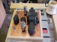
Here we see the finished top plate with everything loaded. We notice a few new things here. 1) Our plate has a shiny copper finish on it. This is a metallic copper base coat with a clear gloss laqeur. I use a lot of laqeur in my finishing as it dries fast. 10 minutes after spraying, you can handle this plate without leaving fingerprints. You must be careful though, laqeur dries hard and will chip before it scratches. I dropped my power socket when I was popping it out and had to sand the whole plate clean and refinish it from scratch. 2) my use of allen, or hex head bolts. These are impossible to strip out and, you don't have to worry about slipping with a screwdriver and scratching the finish on the top plate. I also like them asthetically. Notice the small ones out in the middle of nowhere. They attach three sets of terminal lugs which I have calculated to be useful when I start to wire the circuit. I will include an extra pic showing the bottom of the plate as well. I have also painted all my transformers and one large filter cap flat black, also for asthetics. I removed the end bells on the big power transformer to clean the varnish off before I painted it. I have had to do this with just about every transformer I get from Hammond as they are not shy with the varnish. Drop them in a bucket of acetone for 15 minutes and use a paint brush to brush it right off. A word of caution about brushing acetone, wear some sort of eye protection and do not touch the center coils and windings of your transformer with acetone. It will eat the insulation and varnish right off, destroying your transformer. 3) All my connectors lined up neatly across the back. Bear in mind that with a metal top plate you must have insulators and they must work, you can check them after you mount them with an ohmeter to ensure they do not make contact with the plate (bad things will happen). You can also make a small plate for the back and cut out the wood and put them there, it's just easier for me to do it on top. I had to spin some of my sockets 180' degrees so that the logo's on the tubes would face forward. That about sums it up
Here we see the finished top plate with everything loaded. We notice a few new things here. 1) Our plate has a shiny copper finish on it. This is a metallic copper base coat with a clear gloss laqeur. I use a lot of laqeur in my finishing as it dries fast. 10 minutes after spraying, you can handle this plate without leaving fingerprints. You must be careful though, laqeur dries hard and will chip before it scratches. I dropped my power socket when I was popping it out and had to sand the whole plate clean and refinish it from scratch. 2) my use of allen, or hex head bolts. These are impossible to strip out and, you don't have to worry about slipping with a screwdriver and scratching the finish on the top plate. I also like them asthetically. Notice the small ones out in the middle of nowhere. They attach three sets of terminal lugs which I have calculated to be useful when I start to wire the circuit. I will include an extra pic showing the bottom of the plate as well. I have also painted all my transformers and one large filter cap flat black, also for asthetics. I removed the end bells on the big power transformer to clean the varnish off before I painted it. I have had to do this with just about every transformer I get from Hammond as they are not shy with the varnish. Drop them in a bucket of acetone for 15 minutes and use a paint brush to brush it right off. A word of caution about brushing acetone, wear some sort of eye protection and do not touch the center coils and windings of your transformer with acetone. It will eat the insulation and varnish right off, destroying your transformer. 3) All my connectors lined up neatly across the back. Bear in mind that with a metal top plate you must have insulators and they must work, you can check them after you mount them with an ohmeter to ensure they do not make contact with the plate (bad things will happen). You can also make a small plate for the back and cut out the wood and put them there, it's just easier for me to do it on top. I had to spin some of my sockets 180' degrees so that the logo's on the tubes would face forward. That about sums it up
Attachments
Bottom of Loaded Top Plate
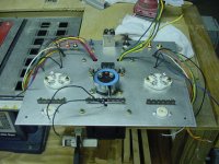
As promised, the bottom side. It is left unfinished to ensure a good common ground. Here is the link to the circuit schematic at Gabevee's site. http://gabevee.tripod.com/2a3diy.html
As promised, the bottom side. It is left unfinished to ensure a good common ground. Here is the link to the circuit schematic at Gabevee's site. http://gabevee.tripod.com/2a3diy.html
Attachments
Re: RUNNING CONSTRUXION.
Thanks Frank, and everyone feel free to chime in with any questions.
fdegrove said:Hi,
Very good idea PF.
And nice work too...
Thanks Frank, and everyone feel free to chime in with any questions.
Re: Finalizing the Top Plate
I love the copper plate and wooden sides.
Hoo-boy! PassFan has every base covered.PassFan said:I had to spin some of my sockets 180' degrees so that the logo's on the tubes would face forward.
I love the copper plate and wooden sides.Thanks for starting this thread, these pictures are most helpful. I'll be taking the plunge and trying my first scratch-built amp soon (and it'll be a 2A3 SE too, probably the Angela/JE Labs one), so this is exactly the kind of information I'm looking for.
Questions:
* That large cap, which one is it? Is it the 10,000uF that's on the 5V supply? Also, a question about the clamps you used for mounting the cap - what are they called, and where can I get them? Does the hole for the cap need to be really snug, or does the clamp hold it pretty well? I've built a couple of kits so far, but never tried mounting a cap that way.
* Painting the cap and transformers - the cap's easy, but could you describe painting the transformers in a little more detail? Is that just flat black spray paint? What did you drop into the acetone - just the bell end caps, right? How about the laminations - do they take paint with no problems? Any special precautions when taking the end caps off? And did you do anything special to the output transformers and PS choke, or just spray painted them?
OK, that ended up being quite a few questions
Thanks,
Saurav
Questions
Saurav:
I'm glad this will help, now to the Questions:
1) You are correct about the cap, it is the 10,000 mf 35 volt. It is actually 21000mf 35 volts but I had some lying around not doing anything so hopefully I can save a little money. They are called, mounting clamp, they should however be found on the same page, in the catalog, as the capacitor you buy and will have a catalog number. Make sure you double check the size matches the cap you buy (I hate ordering the wrong stuff). The hole is slightly larger than the cap, if not it will scrape the paint off the cap. Leave the mounting screws loose until you tighten the clamp around the cap and then tighten them up. It will hold the cap until the end of the world.
2) The output transformers and choke I painted with your typical flat black, nothing special here. I did peel the manufacturers tag off first and they peeled off without leaving any goo behind. Use a couple of light coats instead of one thick one as to avoid runs. If you look at the power transformer you see just four bolts holding it together. These must be removed and the best way will be with a box end wrench or a nut driver and a screwdriver. they are stiff because hammond is never shy with varnish and they get it on the threads too. That is why I never try to hold the nut with pliers. One slip and you could scratch a bell. You will note that the bolt head will have a fiber washer, protect this with your life and make sure it goes back on when your done. This serves to insulate the bolt from one bell, in a way, and needs to be put back on. The laminations can be cleaned and painted but care must be used. To clean the laminations I put a little acetone on a rag (just enough so it doesn't drip, just slightly damp) and rub just the part you will see when the bells are put back on. The same with the paint, you only need to spray what you will see when you put the bells back on. Now it won't hurt to get paint anywhere else as you can see I shot the others transformers up pretty good. After you remove the bolts use a small screwdriver in the gap and just be persistent. The bell will finally let go and you shouldn't have to overforce them to the point of bending anything. They will just pop off. On some older transformers that have been in use for years and overloaded or run hot, they stick and there is little you can do, but on a brand new one they will pop right off. Once off just drop them right in the acetone and let them soak for 15 minutes. The varnish will brush right off leaving them nice and smooth.
If you do a search for "JE Labs" you will find Joseph Esmireldas (SP.) site. He designed the 2A3 at Angelas site and that is his web page. He has lots more info there and seems like a really nice guy. Have fun.
Gabevee said:Wow. That is beautiful work.
Gabe
Thanks Gabe. I owe it all to you. You infected me with the virus, the tube amp bug that all who know and love the sound of glass are infected with.
Skippy, that's looking good.
I recently tried to put a P/S choke (159P) in the same spot you have yours, with a Hammond 373BX PT.
Powering up the transformer, and measuring AC induced in the choke with my DVM, I was getting huge hum -- like 70, 80, 90 millivolts, no matter which way I oriented the choke lams. Out on the corners of the chassis, where you have your tube sockets, was better, but still around 25mv.
Weird, huh? Have you measured yours?
I'm not sure what to do. I'm building parafeed monoblocks with Magnequest output iron. I have the single OPT where you have yours, and the plate choke where you have your other OPT. These are the only two "quiet" spots on the chassis.
I may mount the PS choke under the chassis, directly under the plate choke, and pray I don't get too much coupling. I'll probably start with a CRC power supply, and then switch to the plate to see whether it makes things better or worse.
Well CRAP. How do they get away with the enclosed ones they put on the top on some amps. This may call for a redesign of the top plate. Folks, that's what this hobby is all about, living and learning. I will contemplate all this tommorrow. We will continue on one way or another.
My measurements indicated little reduction in induced AC by putting it under the chassis plate at the current location, or by putting it under the power transformer.
Given that you've had success under the chassis in this spot, and Gabevee has had success under the PT, maybe the amount of 60Hz AC induced in the choke is inconsequential to the AC blocking function of a choke in the CLC filter?
After all, we can replace the choke in a CLC filter with a resistor of equivalent resistance and still get MOST of the ripple reduction you get with a choke. The caps shunt boat-loads of AC noise to ground. Maybe a little 60hz stuff just doesn't matter.
Given that you've bought the parts and drilled the chassis, I'd vote you try it and see. If it's noisy, you can pop in a resistor instead. If it's still noisy after that, $35 will get you one of the Bottlehead C4S kits to put on the plates of the driver tube (assuming your PS can spare a couple ma of current), which I bet will get you down to 2mv AC on the speaker terminals.
You guys seem to be saying that a power transformer and choke cannot share the same chassis, which is definitely not the case. 
Have you tried making sure the bell ends are grounded? I mean really sanding off the paint + varnish on the feet too assure a metal on metal contact.
I regularly place the PSU choke next to the power tranny and I have not had hum problems on those amps.
Have you tried making sure the bell ends are grounded? I mean really sanding off the paint + varnish on the feet too assure a metal on metal contact.
I regularly place the PSU choke next to the power tranny and I have not had hum problems on those amps.
- Status
- This old topic is closed. If you want to reopen this topic, contact a moderator using the "Report Post" button.
- Home
- Amplifiers
- Tubes / Valves
- Running Tube Amp Construction