Hi All
Looking for a simple EL34 Push pull design. I have spent hours searching the net (and this forum) but not yet found anything suitable.
Background is that in late 1992 I purchased a kit to make a directly coupled hybrid transister valve amp. This was featured in Sep 1992 edition of ETI (Electronics Today International) and was designed by a Jeff Macaulay. A kit was available for what was then GBP 170 (at lot of money to me at the time when I was a poor student).
I do not understand more than the the basics of electrical theory but am able to follow a schematic and completed the kit without difficulty. The result was disappointing to say the least. Later additions of the magazine slated the design but following the suggested modifications of other readers I was able to get it working and was reasonably happy with the sound quality. I followed this kit with a Maplin valve pre-amp and the two have served me well all the years in-between. Recently the amp has stopped working due to a fault in the power supply and I have decided that if I go to the trouble of fixing it I would also like to rebuild it to a better design re-using the EL34s and the output tranformers and the rebuilt power supply.
The design uses two EL34s per channel in push/pull configeration but the output transformers do not have ultralinear taps (?triode mode).
I am looking for a circuit therefore which can re-use these valves and the output transformers. I do not want to use a transistor first stage / phase splitter as in the original. All the designs on the internet I can find use either ultralinear configeration or are single ended.
I do have some ECC83, ECC82 and ECF82 valves which I could utilise in the first stages to save a few pounds but this is not mandatory.
Sorry but I do not currently have a scanner and so cannot post the circuit design of the original.
My introduction to valve amplification has been somewhat troubled and drawn out, seemingly by a poor design but I would like to give it another go so to speak.
Any help appreciated. If nothing is forthcoming I will probably have to give up an build a GainClone!
Regards
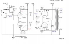
This is as simple as a pp design can get: http://s136.photobucket.com/albums/...on=view¤t=tubeampel38recentcomplete.png
I´m listening to it quite loud as i type this and it sounds awesome.
Just skip the ultralinear and replace the screen resistors whith 220ohm ones and tie them to B+, then bias to 70mA combined for both tubes.
I´m listening to it quite loud as i type this and it sounds awesome.
Just skip the ultralinear and replace the screen resistors whith 220ohm ones and tie them to B+, then bias to 70mA combined for both tubes.
My next project is going to be Poindexter's EL34 music machine amp. Triode PP EL34's around 16 watts or so IIRC. I have seen two versions of this design, one with 6SN7's and one with 6GK5's.
The 6GK5 schem has a CCS (which is the design I am planning on building) Output transformers either 5Kohm or 6Kohm.
If your existing chassis uses 9 pin driver tube sockets hopefully some of the experts here can chime in with other recommendations since the 6GK5's are 7 pin and the 6SN7's are octal.
Poinz' write-up indicates that 9 pin front end tubes were an earlier incarnation of this, you may want to email him and ask.
His email is on his website at www.audiotropic.net
All of the comments I have heard about this deisgn have been very positive.
Here is the link to the 6SN7 version:
http://www.audiotropic.net/Projects/ampEL34.html
If you want a dynamic sounding simple amp without NFB you will have to get rid of the terribly unlinear ECC82. The investment in one 6DJ8/E88CC per channel should be no problem. The same guy that did the AI series 500 is behind this one.
With the right OPT this one will deliver over 10W ClassA with below 1% THD.
If going only Class A you can save money by skipping the EL34 cathode cap.
If you want to try other OPTs it can be adopted to be used with a 115+115:6//6V 50VA mains toroid as OPT. The EL34 cathode circuit will then need some sand to get equal current through both tubes.
By the way, do you now the impedances and other data of your OPT?
Sensitivity is on the low side but I suppose you have preamp? If not, it could easily be constructed using a single 6H30 together with two Lundahl LL1544A.
Attachments
The Audio Tropic design is not without problems. It's basically a Mullard 5-20 with an SRPP substituted for the input tube and the grid stoppers removed. There are a lot of ways of improving it, especially with regard to distortion and source impedance. The SRPP has its niche (high voltage swings into reactive loads), but there seems to be a fascination with it that transcends the actual virtues. The reality is that the input stage needs only swing a few volts, high gain there is a virtue, and for those conditions, a simple triode voltage amplifier (though less sexy and exotic) will be quieter and more linear.
If it were me and I were restricted to published and proven designs (rather than designing my own), I'd go pentode and use the Curcio ST70 design published in Glass Audio (volume 1, number 1, page 1).
If it were me and I were restricted to published and proven designs (rather than designing my own), I'd go pentode and use the Curcio ST70 design published in Glass Audio (volume 1, number 1, page 1).
Checked and the Curcio is a lot of money these days.!
Also remember Jack lives inside EU in GB. This totally rules out the Curcio pricewise.
Some might like the cascodes, I don´t in this applicaton. Tried them both in ST-70 and Mk-IV many years ago when Curcio was in fashion.
But I love them as input-stages in my guitar-amps") !
!
Also remember Jack lives inside EU in GB. This totally rules out the Curcio pricewise.
Some might like the cascodes, I don´t in this applicaton. Tried them both in ST-70 and Mk-IV many years ago when Curcio was in fashion.
But I love them as input-stages in my guitar-amps
!SY said:The Audio Tropic design is not without problems. It's basically a Mullard 5-20 with an SRPP substituted for the input tube and the grid stoppers removed. There are a lot of ways of improving it, especially with regard to distortion and source impedance. The SRPP has its niche (high voltage swings into reactive loads), but there seems to be a fascination with it that transcends the actual virtues. The reality is that the input stage needs only swing a few volts, high gain there is a virtue, and for those conditions, a simple triode voltage amplifier (though less sexy and exotic) will be quieter and more linear.
If it were me and I were restricted to published and proven designs (rather than designing my own), I'd go pentode and use the Curcio ST70 design published in Glass Audio (volume 1, number 1, page 1).
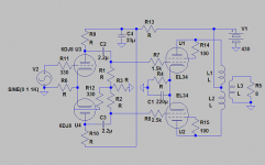
SY: Poinz's 6GK5 schem is attached. Any comments/improvements on this design? I have a pr of hashimoto HW-60-5 (60 watts, 5K) Output tranformers, a quad of EL34's, KT88's, and 6550's and misc driver tubes so I am open to suggestions. I am comfortable designing the PS but I would like to use a published and proven design for the rest. I am looking for a triode design. (pretty much the same as the OP)
Attachments
A CCS diff amp is an excellent way to go SE to PP. I know that it violates his philosophy, but I'd sure want to put grid-stoppers in.
Understand that this circuit will not be good for all loudspeakers because of the low damping factor. I'd guess that it would pair best either with sealed boxes with lowish QTc or as a treble amp in a biamp setup.
Understand that this circuit will not be good for all loudspeakers because of the low damping factor. I'd guess that it would pair best either with sealed boxes with lowish QTc or as a treble amp in a biamp setup.
SY said:Understand that this circuit will not be good for all loudspeakers because of the low damping factor. I'd guess that it would pair best either with sealed boxes with lowish QTc or as a treble amp in a biamp setup.
Or almost all the diy designs in the FR forum, on the frugal-horn site, and many on the p10-hifi site.
dave
A tried and proven performer is my PP-1C design. The two tricks are the use of a cascode gain/driver stage, which really does improve the sonics over any non cascode topology - and the odd layout around the cathodes of the output tubes.
This makes the amp into a quasi differential amp, with all those advantages, but also allows some peak currents to flow on loud passages, while a full differential design is only pure Class A1.
Will work fine with the iron and chassis you have.
The schematic is at:
http://www.vacuumstate.com/index.tpl?rubrik=8&lang=2&a=%B3%3C%B1%BC%C3%11m%D3&b=733737.7121998302
Scroll down to the bottom of that page, past all the interesting preamp designs.
Regards, Allen (Vacuum State)
Take a look on my website for the ST-70 driver circuit listed there, works great with triode connected EL34 and uses a single ECC83 and two ECC82 for a stereo amplifier. It's quite an old design and bears more than a passing resemblance to the Mullard 5-20 circuit. It can be adapted to cathode biased EL34 without difficulty..
Link here: http://www.kta-hifi.net/projects/amp_page/st70amp/st70.html
Design works just fine with point to point wiring - you do not have to make a pcb.
I sold something like 100 kits before I discontinued the business and many people have also made their own clones based on the information here..
Link here: http://www.kta-hifi.net/projects/amp_page/st70amp/st70.html
Design works just fine with point to point wiring - you do not have to make a pcb.
I sold something like 100 kits before I discontinued the business and many people have also made their own clones based on the information here..
planet10 said:
Or almost all the diy designs in the FR forum, on the frugal-horn site, and many on the p10-hifi site.
dave
Planet10: I'm not sure I got your point.......the design pairs good with these or doesn't have enough damping for these?....
Allen Wright said:A tried and proven performer is my PP-1C design. The two tricks are the use of a cascode gain/driver stage, which really does improve the sonics over any non cascode topology - and the odd layout around the cathodes of the output tubes.
This makes the amp into a quasi differential amp, with all those advantages, but also allows some peak currents to flow on loud passages, while a full differential design is only pure Class A1.
Will work fine with the iron and chassis you have.
The schematic is at:
http://www.vacuumstate.com/index.tpl?rubrik=8&lang=2&a=%B3%3C%B1%BC%C3%11m%D3&b=733737.7121998302
Scroll down to the bottom of that page, past all the interesting preamp designs.
Regards, Allen (Vacuum State)
Allen: I actually have your PP-1C schematic on my desk...I have a note scribbled on it that it's around 8W class A, is that correct? (I have no idea where that came from..)
BW, you asked:
>I have a note scribbled on it that it's around 8W class A, is that correct? (I have no idea where that came from..)<
I seem to remember 10-12 watts, but it's 10 years since I built one.
It was intended as a very low priced kit for Malaysian DIYers through our Malaysian agent, but doing it again I would certainly up the B+ voltages to +400, but no other changes.
If you wanted to do it right, then use a choke input filter, as we use in our PP-2C design, and all our commercial products.
Regards, Allen (Vacuum State)
I've seen the measurements of Allen's cascodes (and my own and Joe Curcio's). Distortion is quite low and quite low order. So they can be designed properly, though I'll grant that I've sure seen a lot of bad ones. The big issue with them is the lack of power supply rejection, but that's not too big a hurdle for power amp input stages.
Sy,
It is easy to see by using FFT that cascoded are a lot worse than the same config´d triode. As for Mr. Wrights I did a sim where the FFT was just like his measured. I also did the same with Eriks(Audion, AI etc.) in post 5 and those had a much nicer overtone spectra. This is in theory, if it is the same when you listen to them I can´t say.
I have listened to Curcios (remember this circuit was done in the 70´s) as I did a ST-70 rebuild and I was not impressed. As I said earlier, I love them in my guitaramps TULP-circuit where their overtone spectra come in handy!.
So when you can do something that eventually is better with the KISS principle: Do it!
Lars asks: >Why use cascodes as drivers?<
Because they sound GREAT!
If you look at the distortion curves published with my amp's schematic, you will not see any great amount of odd order distortion. In fact in our preamps, without a following zero NFB power stage to add significant distortion, the cascode stage normally has distortions lower than 0.005%, also without any NFB!
They just have to be designed right, using the correct tube run at the correct currents and voltages, and that means hi gM tubes at high currents.
Regards, Allen (Vacuum State)
- Status
- This old topic is closed. If you want to reopen this topic, contact a moderator using the "Report Post" button.
- Home
- Amplifiers
- Tubes / Valves
- Wanted. Simple EL34 Push Pull Design