I have an idea for a power supply that will require a voltage quadrupler as can be seen here:
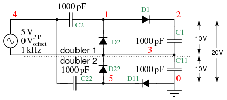
I was thinking of making a hybrid version akin to a hybrid Graetz bridge. In the picture above, is it just D1 that needs to be vacuum? Any unforeseen issues that I am overlooking (voltage ratings already noted)?
I was hoping to gain the slow turn on of the tube rectifier. I was planning to use a diode damper and in this case, just one and all lower diodes silicon.
Depends on what you need it for. A bias supply, maybe...
Just keep in mind you will need to supply it with at least 4 times as much current as the load uses. About the only use for these voltage multipliers is low current very high voltage devices like ion generators. Best to stick with something more conventional.
Just keep in mind you will need to supply it with at least 4 times as much current as the load uses. About the only use for these voltage multipliers is low current very high voltage devices like ion generators. Best to stick with something more conventional.
Josh,
The last circuit shown here will do the job for you. TANSTAAFL applies and the "arm" caps. need to be MPP and the voltage strain on them increases towards the top of the rail. 'Lytics are OK in the central "spine". Insert a damper diode between the multiplier and a final LC filter section.
The last circuit shown here will do the job for you. TANSTAAFL applies and the "arm" caps. need to be MPP and the voltage strain on them increases towards the top of the rail. 'Lytics are OK in the central "spine". Insert a damper diode between the multiplier and a final LC filter section.
JoshK said:
Not sure what "TANSTAAFL" stands for.
"There ain't no such thing as a free lunch" the acronym was originally popularized by sci-fi writer Robert Heinlein..
More here: http://en.wikipedia.org/wiki/TANSTAAFL
The term is used a lot in economics, and is particularly, stingly relevant where credit default swaps are concerned..

Josh,
You say that roughly 900 V. is the B+ target. Figure on about 1.3X the RMS voltage per multiplier stage, as the rail voltage. The 240 VRMS your power "iron" offers should be tripled, according to my math.
You are definitely safe using the 660 VAC caps. in the 2nd stage "arm" positions. IMO, it's cutting things a bit too fine to use them in the 3rd stage "arms".
Thanks for the guidance. Its brainstorming stage at the moment. I have the iron to use, but then it is getting tricky.
I was estimating 4 x 240 = 960 which gives some room for losses across choke(s) but forgot about the bridging effect cause I was initially looking at choke input.
I was estimating 4 x 240 = 960 which gives some room for losses across choke(s) but forgot about the bridging effect cause I was initially looking at choke input.
Yeah I get that. Actually I was referring to having modeled a choke input psu in PSUDII to see what secondary I'd need before I thought I'd look into a voltage multiplier for iron I already had. The signal DU 1/2's are pretty big chunks of iron so I thought it might have enough current to burn.
When I was trying to figure out the secondaries, I had .9 in the brain for a choke input and forgot when I switched to thinking about multipliers that the figures I had in my head needed modification. Too many years of studying math and one can't do arithmetic anymore.
When I was trying to figure out the secondaries, I had .9 in the brain for a choke input and forgot when I switched to thinking about multipliers that the figures I had in my head needed modification. Too many years of studying math and one can't do arithmetic anymore.
JoshK said:Well the transformers intended to be used are signal DU1/2, i.e. 120 > 240 volt 500w transformers. I was considering putting the quadrupler on this transformer to step up to ~900ish for an 813 set amp.
If you're going to go to all that trouble, then don't be so cheap and pop for the proper power xfmr. With voltage multipliers, the regulation SUX, and they're inefficient. With a triode final, you're gonna need a PS with good regulation. You can sometimes get away with a worse PS with pentode finals since the plate current is relatively independent of Vpk. Not so with triodes, and bad regulation is a serious sonic compromise.
- Status
- This old topic is closed. If you want to reopen this topic, contact a moderator using the "Report Post" button.
- Home
- Amplifiers
- Tubes / Valves
- Hybrid voltage quadrupler?