what CCS are you using? I've had good results with Morgan Jones one in his Valve Amplifiers book. He uses a pair of BC149, a pair of red LEDs and a couple of resistors. He recommended the J511 but that's not available any more and I don't know the equivalent.
Damn good tube the ECC40 - I've used in in differential pair and its a really good sound. Lovely treble.
Andy
Damn good tube the ECC40 - I've used in in differential pair and its a really good sound. Lovely treble.
Andy
Hi Andy
Maybe these diodes will work?
http://www.diyaudio.com/forums/showthread.php?s=&threadid=123037&highlight=
I have no affiliation with the seller...
Erik
Maybe these diodes will work?
http://www.diyaudio.com/forums/showthread.php?s=&threadid=123037&highlight=
I have no affiliation with the seller...
Erik
A plain JFET with gate and source tied together (that's what the J511 is anyway) will work fine for that application. To be honest, I think that the performance difference between a CCS feed of the LED string and just using a large-value resistor tied to B+ will be negligible. The CCS feed is more appropriate for low voltage situations where the resistor would need to be something like 1k instead of 100k.
A plain JFET with gate and source tied together (that's what the J511 is anyway) will work fine for that application.///
That's what I'm after - do you have a model number of an appropriate one?
Erik's right - the J511 is on p134(c) of MJ's book. I use the version with two BC549, two red LEDs and a multi-turn sensor potentiometer. The bottom of the string goes to -15v and the top via the J511 to earth. It's possible to replace the J511 with a resistor, but an equivalent of the J511 would be good to try.
andy
You can do it three ways: find a 50V FET with an Idss somewhere nearby and do some selecting, find a 50V FET with an Idss higher than you want and use a source resistor to bias it correctly, or (my choice) use any old 25 or 30V FET with a series resistor to drop most of the voltage, leaving 10V or so across the FET. The rationale is that there are hundreds of usable 25V FETS, but very few 50V ones.
Alternatively, you could use a DN2540 with a source resistor. Overkill, but they're cheap.
One more thing to consider is a cascode of DN2540 instead of the bipolar CCS. No reference string, super low parts count and expense, extremely good performance. I've seen some fancy ones, but I've posted schematics of a dead simple one, just two FETS and four resistors. I suspect that you'll see this circuit in the 4th edition of Valve Amplifiers.
the ccs is not the problem
I would like to use an interesting power stage with 6CB6A pentode driving a pair of el34's in push pull with local feedback. It is published in Glass Audio 4/95 (design Berglund). See attachment.
Perhaps I try a regulated screen supply on grid 2 of the el34's.
As a splitter before this powerstage I thought of a ecc40 LTP with ccs under it. B++ will be between 300 and 400 Volt.
Problem is what operating point, component values, etc.
First question is: is this constellation feasible ?
hemgjord said:It would look like any diff stage. If you want suggestions regarding komponent values, operating points etc. I think you have to be a little more specific as to the intended use, available rail voltages etc.
/Olof
I would like to use an interesting power stage with 6CB6A pentode driving a pair of el34's in push pull with local feedback. It is published in Glass Audio 4/95 (design Berglund). See attachment.
Perhaps I try a regulated screen supply on grid 2 of the el34's.
As a splitter before this powerstage I thought of a ecc40 LTP with ccs under it. B++ will be between 300 and 400 Volt.
Problem is what operating point, component values, etc.
First question is: is this constellation feasible ?
Attachments
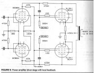
Yes, the circuit is certainly feasible. I'm modeling it right now with LTspice, using 6SN7 LTP splitter with BJT cascode CCS tail, 6AU6 drivers and EL34 outputs. I think the OP transformer should be for 3.5k p-p load, not 5k. With B+ = 480v at the OP transformer CT, available power is 54w with input signal of 900mV amplitude (630mV RMS) @ 1kHz.
It models well with added global NFB and some jiggering around with correction networks to remove the peaks at low and high frequencies. I use a step-network to couple the LTP to the pentode drivers, because that gives better LF stability for my purposes. Adjustment is necessary to the shared cathode resistor of the drivers, because the step network elevates the grid and cathode voltages.
It models well with added global NFB and some jiggering around with correction networks to remove the peaks at low and high frequencies. I use a step-network to couple the LTP to the pentode drivers, because that gives better LF stability for my purposes. Adjustment is necessary to the shared cathode resistor of the drivers, because the step network elevates the grid and cathode voltages.
SY said:You can do it three ways: find a 50V FET with an Idss somewhere nearby and do some selecting, find a 50V FET with an Idss higher than you want and use a source resistor to bias it correctly, or (my choice) use any old 25 or 30V FET with a series resistor to drop most of the voltage, leaving 10V or so across the FET. The rationale is that there are hundreds of usable 25V FETS, but very few 50V ones.
Alternatively, you could use a DN2540 with a source resistor. Overkill, but they're cheap.
One more thing to consider is a cascode of DN2540 instead of the bipolar CCS. No reference string, super low parts count and expense, extremely good performance. I've seen some fancy ones, but I've posted schematics of a dead simple one, just two FETS and four resistors. I suspect that you'll see this circuit in the 4th edition of Valve Amplifiers.
Very helpful post. Can I ask where you posted the schematics for your DN2540 cascode? Or could you post them again in this thread? I have some IXYS 10M45S. Can these be just dropped in for the DN2540 or do they require anything different. I'm quite ignorant of solid state, so may need a bit of hand holding here!!
andy
Here it is. The two gate resistors are gate-stoppers, value not critical but keep the resistor bodies as close to the gate lead as possible. R5 sets the current- for the particular batch of FETs that I got, 300R yielded a 10mA current. That might be different with a different batch, so I'd set up a test jig and pick a resistor to get you the right set current. I found that once I determined the right resistor value, all the FETs in that tube gave me pretty close to the same current.
Attachments
1. I haven't used that device, but if it's a depletion mode device, it'll work. You'll just have to determine the correct bias resistor value.
2. I'd want more voltage across it, especially because of the signal knocking out a volt or two of the headroom. Either a separate negative rail (easy and noncritical, since the CMR of a diff amp is high, and the CCS itself forms a divider with the looking-in resistance of the cathodes) or lifting the grids above DC ground by a few volts (also easy with a voltage divider). Same with the bipolar unit- you want at least 5V across it, more would be better.
2. I'd want more voltage across it, especially because of the signal knocking out a volt or two of the headroom. Either a separate negative rail (easy and noncritical, since the CMR of a diff amp is high, and the CCS itself forms a divider with the looking-in resistance of the cathodes) or lifting the grids above DC ground by a few volts (also easy with a voltage divider). Same with the bipolar unit- you want at least 5V across it, more would be better.
- Status
- This old topic is closed. If you want to reopen this topic, contact a moderator using the "Report Post" button.
- Home
- Amplifiers
- Tubes / Valves
- ecc40 LTP