Hi folks,
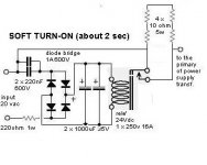
I have an irritating problem with this soft start circuit.
I have breadboarded it up and it seems to work with a light bulb load but when I was checking the relay coil voltage, I noticed that it just kept climbing. I shut it down when it got to about 31V
Mutliple tests, swapped all components (except relay which is new) same result - the voltage climb rate is slow - it takes maybe 180 sec to increase from 24 to 31V but never looks like reaching a plateau, just a slow steady climb. Have tested with heavier loads with the same result
The coil is rated at 24 volts as per the schematic. I increased the 220 ohm resistor to 240 ohms (using 240AC input), otherwise the circuit is identical.
Does anyone have any idea what is going on? Obviously I am concerned that if the voltage keeps rising it will burn out the relay coil, the 35V caps or both.
Thanks for any input this is bemusing me.
Rob
I have attached the slow start circuit, it is from Andreas 845 amp.
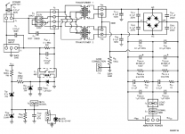
The full circuit diagram is here -
http://www.audiodesignguide.com/New845/New845v2.html
I have an irritating problem with this soft start circuit.
I have breadboarded it up and it seems to work with a light bulb load but when I was checking the relay coil voltage, I noticed that it just kept climbing. I shut it down when it got to about 31V
Mutliple tests, swapped all components (except relay which is new) same result - the voltage climb rate is slow - it takes maybe 180 sec to increase from 24 to 31V but never looks like reaching a plateau, just a slow steady climb. Have tested with heavier loads with the same result
The coil is rated at 24 volts as per the schematic. I increased the 220 ohm resistor to 240 ohms (using 240AC input), otherwise the circuit is identical.
Does anyone have any idea what is going on? Obviously I am concerned that if the voltage keeps rising it will burn out the relay coil, the 35V caps or both.
Thanks for any input this is bemusing me.
Rob
I have attached the slow start circuit, it is from Andreas 845 amp.
The full circuit diagram is here -
http://www.audiodesignguide.com/New845/New845v2.html
Attachments
Hi Frank,
Did that - even increased to 1k. with a 4W resistor. Little change but the resistor got pretty hot. The relay draws 20 mA and this may be the problem I think. I did a quick calculation and got a value around 11K at 4.4W.
May try a couple of resistors in series to see what happens.
Rob
Did that - even increased to 1k. with a 4W resistor. Little change but the resistor got pretty hot. The relay draws 20 mA and this may be the problem I think. I did a quick calculation and got a value around 11K at 4.4W.
May try a couple of resistors in series to see what happens.
Rob
don't use the raw mains to feed the delay side of the relay.
Use a separate 20Vac transformer that comes on with the power switch.
Keep the mains side to the relay contacts.
Live comes to one relay contact and Live leaves the other relay contact.
Edit:
your posted schematic is misleading. It has omitted the 2 from 220Vac to leave 20Vac showing.
I still do not recommend using mains by that method.
Do you realise what will happen if one or both of those caps starts to fail to shorted?
Edit2:
the 240Vac mains ~340Vpk.
at 240Vac the 440nF caps pass~46mA. At this current draw the 220r resistor drops 10V. That leaves ~330Vpk to charge the 35V caps.
If the relay draws that 46mA then it stabilises the voltage across the caps. But if the relay current does not balance the supply through the caps the bridge will keep on charging the smoothing to >300Vdc. Eventually the smoothing cap leakage will balance out the total current passing the 440nF.
But what happens in the meantime?
We could modify the circuit for better operation. But that still leaves a dangerous situation for anyone that chooses not to follow the modifications to make it safer and more reliable.
I am going to report this post to the Moderators.
Thanks for the advice Andrew.
Sorry about the schematic, you are correct, it should read 220VAC. I chopped the 2 off the front whilst copying.
I just used 4 x 2.2K 4W resistors in series with good results, so the problem clearly is the resistance of my coil (thanks Frank). Whilst this did work the resistors still got pretty hot.
Andrew, I like your idea of the 20VAC transformer. I need 12V for my LEDS , so I might get a center tapped 20 V transformer to run both the LEDS and the soft start relay.
With regards to the caps failing with the mains, I did not tink it through and it is now 2 am so can't think straight but by the sounds of your email it is obviously not something good .
.
Thanks again,
Rob
Sorry about the schematic, you are correct, it should read 220VAC. I chopped the 2 off the front whilst copying.
I just used 4 x 2.2K 4W resistors in series with good results, so the problem clearly is the resistance of my coil (thanks Frank). Whilst this did work the resistors still got pretty hot.
Andrew, I like your idea of the 20VAC transformer. I need 12V for my LEDS , so I might get a center tapped 20 V transformer to run both the LEDS and the soft start relay.
With regards to the caps failing with the mains, I did not tink it through and it is now 2 am so can't think straight but by the sounds of your email it is obviously not something good
.Thanks again,
Rob
If you MUST use capacitors, use safety rated "X" capacitors, which are rated for mains use. Essentially, they act as a 30 mA constant current source, so as the relay coil heats (and its resistance rises), it consumes more power, which makes it even hotter... add a 24V zener diode in parallel with the coil.
AndrewT said:[BShould we be advising on altering a potentially dangerous schematic? [/B]
Indeed. Since the poster has indicated that the circuit is attached to the mains the thread should be closed IMHO.
leadbelly said:
Indeed. Since the poster has indicated that the circuit is attached to the mains the thread should be closed IMHO.
So we'll only discuss battery operated amplifiers from now on? Mains circuits should use components rated by safety agencies for the purpose. I see no reason that can't be done with the original circuit (of course there may be a BETTER circuit - isn't there always?).
As for the zener getting hot, it will see about 10 mA at 24V - 0.24W
Leadbelly,
The poster (me) was asking for advice on a schematic designed by a reputable and experienced designer on this thread, so yes, I did indicate it was connected to the mains as was the original intention of the designer. There are several similar soft start schematics around. I do see the problems with the circuit and will modify accordingly using low voltage to drive the soft start side of the circuit.
Yes, the mistake I made was stupid in retrospect but that's why I test everything that I build with great care. The mistake was identified and corrected. I did learn something.
Closing a thread that has the potential to improve the safety of a widely publicized circuit is mistake IMHO - in my case I will change to low voltage supply, surely a good outcome?
Rob
leadbelly said:Indeed. Since the poster has indicated that the circuit is attached to the mains the thread should be closed IMHO.
That's going a bit too far. The schemo clearly indicates that there is no connection anywhere between the DC output and the main power supply neutral. As long as it's floating, it presents no shock hazard (unless you're servicing that subsystem and you'd be prudent enough to use an isolation xfmr while doing so, wouldn't you?)
I think the thing is overly complex, as a simpler design will work just as well and have a longer delay. Of course, whenever you have anything connected across the mains, whether it's a soft start or a MOV, you need a fuse ahead of it as well as ahead of the power supply switch. In any case, you should always fuse everything anyway, even if it does run on batteries as some batteries (Lead acid; Ni-Cads) can source some hellacious currents if dead shorted.
AndrewT said:go and read ESP for safer ideas on soft starting and his warning on using mains power for the delayed bypass relay.
Rob11966 said:Fused of course. I am simplifying this somewhat with a low voltage coil supply as outlined below. You mentioned a simpler design with longer delay, anything you can direct me to easily?
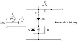
This type of soft start has been in use for a dog's age. As you can see, it can't over volt like that other one since R1 and the DCR of the relay coil form a voltage divider. CR1 serves as a simple half wave rectifier to feed DC to the relay coil. CR2 serves as kickback protection at power down.
The delay time is set by the timing capacitor and R1 || DCR. Figure that it takes ten RC time constants to charge up to the coil's pull-in voltage (usually 12 or 24 Vdc depending on what relay you have). Of course, you don't have to be super accurate with the timing, and most relays will pull in at some voltage under the nominal coil voltage. Still, not too difficult to get delays of 10 -- 30 secs with this.
Attachments
Miles Prower said:That's going a bit too far. The schemo clearly indicates that there is no connection anywhere between the DC output and the main power supply neutral. As long as it's floating, it presents no shock hazard (unless you're servicing that subsystem and you'd be prudent enough to use an isolation xfmr while doing so, wouldn't you?).
Now THAT is going to far. If we use that logic, then all the 2 pronged 50EH5 amps with no isolation are open game on this forum.
leadbelly said:Now THAT is going to far. If we use that logic, then all the 2 pronged 50EH5 amps with no isolation are open game on this forum.
Big difference there. The 2 pronged 50EH5 amp has at least two user connections: the speeks and the input. He will potentially come into contact with a hot chassis at either end. Besides, the sonics of these things is pure
An externally hosted image should be here but it was not working when we last tested it.
and wouldn't be a subject here.
About the only device where it really wouldn't matter would be a radio xcvr with an integral antenna where the end user connects nothing. Even there, you can't be certain he wouldn't try to mod it and break the isolation or otherwise do something stupid.
Still, I wouldn't build anything like that anyway. 50EH5s run better with higher plate voltages, and require a power xfmr to jack the Vpp up to a point where you're running in the most linear part of the characteristic. If you're gonna do it, do it right or don't bother.
- Status
- This old topic is closed. If you want to reopen this topic, contact a moderator using the "Report Post" button.
- Home
- Amplifiers
- Tubes / Valves
- Irritating problem with soft start