Simple Soft Start
OK,
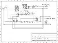
After same debate, here is the final version of the soft start.
The soft start circuit is driven by low voltage supply as seen in the schematic attached.
Bench testing very good with 2.5 second delay. I have over specked the resistors and mounted them on heat sinks and they don't get warm.
I have also included a soft start indicator which lights up green when the soft start part of the circuit is running. I plan to mount it on the back of the chassis and it will indicate blown fuse/damaged relay if not lighting up.
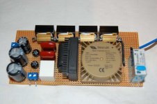
I have included a picture of the layout in the next post.
Rob
OK,
After same debate, here is the final version of the soft start.
The soft start circuit is driven by low voltage supply as seen in the schematic attached.
Bench testing very good with 2.5 second delay. I have over specked the resistors and mounted them on heat sinks and they don't get warm.
I have also included a soft start indicator which lights up green when the soft start part of the circuit is running. I plan to mount it on the back of the chassis and it will indicate blown fuse/damaged relay if not lighting up.
I have included a picture of the layout in the next post.
Rob
Attachments
Hi Rob,
You need to fix the schematic you posted, it clearly shows the lower of the two bridge rectifiers with shorts on both sides of the caps feeding it. More to the point that second bridge and those caps are not really required now.. I would use a single transistor and simple rc time constant to provide the delay required to operate that relay. (Or you could use a 555 timer IC for more flexibility in delay time.)
You need to fix the schematic you posted, it clearly shows the lower of the two bridge rectifiers with shorts on both sides of the caps feeding it. More to the point that second bridge and those caps are not really required now.. I would use a single transistor and simple rc time constant to provide the delay required to operate that relay. (Or you could use a 555 timer IC for more flexibility in delay time.)
Hi Kevin,
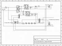
Reposted with apologies.
I was trying to avoid IC's and transistors and to keep it as simple as possible.
Using capacitor values of between 1 and 10uf gave my any delay that I could practically need so I thought that this would be a bit more straightforward than a 555 circuit.
Thanks for the correction.
Rob
Attachments
- Status
- This old topic is closed. If you want to reopen this topic, contact a moderator using the "Report Post" button.