Hi there, having very poor knowledge about electronics, I am not sure if it is a silly question. I'm fiddling with my Marantz ST-450 TUNER and I wonder if it is possible to implement a magic eye tuning indicator in a solid state circuit. What are the possible obstacles trying to feed the tuning signal into indicator tube, how to power the tube without using a separate bulky transformer. Filament won't be the problem, how can I derive the 250V B+ ?
My Marantz ST-450 TUNER uses a led driver IC diving 5 leds as a VU-meter, I canceled that circuit, and implemented a mechanic signal meter successfully. Now I think why not using a magic eye tube instead of a mechanic gauge. As I can guess, an inverting amplifier is necessary to get the signal to 0, -8 range to drive the 1629 display tube, anyway before digging the detail, for the moment I wonder if this idea is possible technically.
Anybody tried something similar? Would be grateful for any opinions-guidance.
Ferhat
Magic Eye tubes mostly need 250V at around 1 or 2 mA.
The heater voltage you MAY be able to tap off the existing power supply, but it a heavy current for a solid state power supply to supply.
The 250V you could get from a voltage multiplier, or a DC-DC converter - but keep it well shielded. I'd prefer to use two small 220:24 transformers back-to-back. You can use tiny ones, as the current is low, and it prevents the possibility of interference from a switching DC/DC converted.
Getting the drive signal correct should be very easy with a single op-amp, configured for the right gain - the eye tube grid probably needs a voltage of around -10v to 0v to bring about a full change in apearance, as you stated. (depends on exactly which tube you use).
A nice project, and not very difficult.
Steerpike put his finger on the most difficult thing, which is the 1629's 150 mA./12.6 V. heater draw. A 200 - 250 mA. "12" V. "wall wart" (either AC or linear DC) will dispose of the problem.
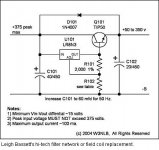
The 1629 data sheet indicates that B+ should be in the 125 - 250 V. range. 6 mA. of available B+ current will surely take care of the needs of the "eye". Scrounge up a low current toroidal power trafo whose O/P voltage is in the 20 - 25 V. range. Use a multi-stage voltage multiplier that follows the 1st example here. Thankfully, this application does not require a super high quality B+ rail.
The 1629 data sheet indicates that B+ should be in the 125 - 250 V. range. 6 mA. of available B+ current will surely take care of the needs of the "eye". Scrounge up a low current toroidal power trafo whose O/P voltage is in the 20 - 25 V. range. Use a multi-stage voltage multiplier that follows the 1st example here. Thankfully, this application does not require a super high quality B+ rail.
I just searched out and looked at pictures of that Marantz. I think it's a Kenwood in disguise.
There is certainly not a big volume of cabinet to it - how much space is there inside?
Where on the front will you make a window for the eye tube?
There are - not sure if you can get them anywhere - some B7G type eye tubes, like the 6ME5, which are smaller than the one you mentioned.
There is certainly not a big volume of cabinet to it - how much space is there inside?
Where on the front will you make a window for the eye tube?
There are - not sure if you can get them anywhere - some B7G type eye tubes, like the 6ME5, which are smaller than the one you mentioned.
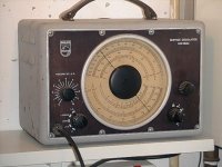
Thanks for the replies everybody. This project started with the idea of giving the tuner a new housing, to keep it short, I put the circuitry of the Marantz tuner inside the case of Philips GM2883 Service oscillator.
The Philips has a very cute look with a big scale, I loved the look but didn't need the function and just the opposite for Marantz tuner. It's a hybrid tuner with analog tuning and a digital frequency display, the flouresant display was broken so I replaced it with 7-segment led displays, adapted the tuning mechanism to the Philips' dial, cut the PCB in two pieces and repositioned it into the new casing, designed a new backlit scale a bit resembling a Chevy speedometer and etc. Eventually it's going to be a very nice looking (of course in my taste) piece of equipment and I think the magic eye will complete the design. I would like to share the photos of the project as soon as I get to my camera.
Now about the B+ problem, the voltage multiplier sounds like a good idea, but my question is what kind of diodes and capacitors should be used and what are the capacitor values?
By the way Richard, thanks for the idea but I'm afraid it exceeds my comprehension, maybe other experts have their opinions on it.
Attachments
Now about the B+ problem, the voltage multiplier sounds like a good idea, but my question is what kind of diodes and capacitors should be used and what are the capacitor values?
Please refer to that 1st multiplier schematic, again. Notice that both diodes and caps. are subjected to equal stress. UF4004 diodes and 50 WVDC/15 μF. electrolytic caps. should be more than adequate for this job. Use decent, industrial grade, parts, not junk.
To get a good idea of the available B+ current, start with 1/2 the AC RMS value of the rectifier winding and divide by the number of multiplier stages used.
Attachments
That Philips box is beautiful! I have the audio range oscillator of the same/similar series - with EFM1 magic eye to null the BFO.
I use it regularly in my audio tests still. It weighs about 20kg, so in most cases it's easier to move the amp in question to the signal generator, rather than the other way round!
I use it regularly in my audio tests still. It weighs about 20kg, so in most cases it's easier to move the amp in question to the signal generator, rather than the other way round!
Hello everybody, finally I found a neat solution to power the magic eye and the whole circuit thanks to a great guy running a small company here in Istanbul. He is producing all kinds of transformers, and he made one for me with multiple outputs. (12 volts for filament, 2X 18 volts for the tuner circuit and 250 Volts for B+) Total load is 10 watts and it only cost 10 TL which is approximately 8 dollars.
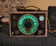
As a result with one transformer, I could power the tuner circuit, the magic eye filament and B+, the amp for feeding the tuning signal into the magic eye and even the display illuminating leds. Behind the display, are 25 leds, series array with a small resistor powered also from the 250 volt output. Now all I need is a pair of speakers matching the retro look of the tuner.
I will put an on/off switch for the magic eye, I don't need it shine all the time, it's a fancy thing as you could guess. Which way is better do you think? Put the switch on B+ or the filament? Or both? Any ideas?
FoKale said:Hello everybody, finally I found a neat solution to power the magic eye and the whole circuit thanks to a great guy running a small company here in Istanbul. He is producing all kinds of transformers, and he made one for me with multiple outputs. (12 volts for filament, 2X 18 volts for the tuner circuit and 250 Volts for B+) Total load is 10 watts and it only cost 10 TL which is approximately 8 dollars.
Stateside, we are always lookin' for folks who are reinventing a better wheel. Tell your friend to open a webstore and he'll be amazed at the number of folks beating a path to his door via PayPal,
- Status
- This old topic is closed. If you want to reopen this topic, contact a moderator using the "Report Post" button.
- Home
- Amplifiers
- Tubes / Valves
- Magic Eye for solid state Tuner?