....
i want to convert 2Vrms, balanced signal to unbalanced audio signal using tubes with no transformer to do the conversion and with gain of arround 1 .... it would be nice to have not to much stages (one stage will be perfect)..... does anybody has a suggestion......
thanks for any help
regards
sunny
i want to convert 2Vrms, balanced signal to unbalanced audio signal using tubes with no transformer to do the conversion and with gain of arround 1 .... it would be nice to have not to much stages (one stage will be perfect)..... does anybody has a suggestion......
thanks for any help
regards
sunny
Hi
The Broskie cathode follower could be an option as well
http://www.tubecad.com/october99/page9.html
Erik
The Broskie cathode follower could be an option as well
http://www.tubecad.com/october99/page9.html
Erik
SY's anser is correct but kinda brief.
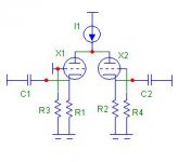
You need a differential stage sitting on a very good current source. That is naturally balanced in on the two grids, and you can have a perfect unbalanced signal on either of the two anodes, one in phase and one out of phase.
Bit hard to only have a gain of one, but you can certainly get it down by using larish unbypassed cathode Rs in the diff pair.
Regards, Allen (Vacuum State)
hmm.... I was in this task on a balanced phono pre amp output a couple of years ago.
I found it to be completely unnecessary to convert to unbalanced with an extra diff-amp buffer.
I ended up with simply using one signal phase, leaving the other phase disconnected.
To me 1Vrms seems plenty sufficient.
Btw, your source is not a transformer output ?
Klaus
I found it to be completely unnecessary to convert to unbalanced with an extra diff-amp buffer.
I ended up with simply using one signal phase, leaving the other phase disconnected.
To me 1Vrms seems plenty sufficient.
Btw, your source is not a transformer output ?
Klaus
Long necked pair, differential "4th circuit".
Shared CCSink above common plates.
This cuts gain down to 1 (or slightly less?).
Output impedance would be favorably low.
And PSRR should be excellent. As good as
your CCS vs output cathode impedance(s).
Referenced almost entirely to GND.
Make sure there is plenty of Mu headroom
for the plates to couple. Voltage swing at
the shared "neck" might be quite large.
Power supply may not need much filtering,
as that chore is redundant to the action of
the common plate current sink. Free bonus.
Unique to the relatively low plate impedance
of Triodes, the plate can be abused as either
input or output, or both simultaneously...
Same basic concept as long tail pair, but
completely upsidaisified, and without any
voltage gain (but lots of current gain)...
Do you need a picture?
----------------------------------------------------
Parts saved include two cathode resistors
(previously suggested to reduce gain to 1).
And almost all power supply filtering, but
perhaps for one cap.
")
I gotta get out and go to work right now.
But when I get home, I'll draw you up an
LTSpice.
Its too damn simple, we speak of only five
components. One shared CCS, two triodes,
each with an independent cathode resistor.
OK OK, so you gotta add grid leak and some
coupling caps... Goes without saying.
But when I get home, I'll draw you up an
LTSpice.
Its too damn simple, we speak of only five
components. One shared CCS, two triodes,
each with an independent cathode resistor.
OK OK, so you gotta add grid leak and some
coupling caps... Goes without saying.
"Long necked pair" = differential cathode follower.
Use a well matched pair of 6GK5s for both high gm and high mu. Tie the plates together and connect via a COMPETENT CCS to B+. Use separate 4X RP load resistors under the cathodes and connect to a B- supply. The negative rail provides both the necessary compliance and also allows for DC coupling, save for the O/P jack(s).
Use a well matched pair of 6GK5s for both high gm and high mu. Tie the plates together and connect via a COMPETENT CCS to B+. Use separate 4X RP load resistors under the cathodes and connect to a B- supply. The negative rail provides both the necessary compliance and also allows for DC coupling, save for the O/P jack(s).
Bal to unbal
Hi:
Just do what I did in the telephone co with video signals , terminate the unused side (the - side ) with a 124 ohm resistor , do the same with the + side and take the unbalanced signal at that point (the + side ).
You have now terminated the balanced line with 124 ohms on each side and now you can take the unbalanced audio from either side actually. The + side for normal signals and the - side for reverse polarity signals.
No complicated circuits just a couple of resistors for terminating the balanced line.
Hope this helps
Ed
differential cathode follower
I have spent quite some time searching for examples of balanced tube crossovers based on cathode followers, but did not find any reference. Then I came across the balanced RIAA stage in Valve amplifiers 3rd edition where MJ uses two simple cathode followers, so I assumed there was no such thing as a differential cathode follower....until today: it is the first time I read about a differential cathode follower. A search at diyaudio did turn up no result... google shows some more, but none related to audio usage.
However, a fast sketch shows that it should work... it looks as a potential candidate for a simple no gain line stage with both balanced and single ended inputs and outputs!
Hello !
In tubecad Journal : http://www.tubecad.com/2006/08/blog0075.htm
There is an schematic (last one) based on JR Broskie CF that I tried, in an balanced voltage DAC output stage (CS4397) with LP filter
I made it simply, with 2 6gm8, and the B+ psu 24v with a lm317
Works perfectly !
R.C.
In tubecad Journal : http://www.tubecad.com/2006/08/blog0075.htm
There is an schematic (last one) based on JR Broskie CF that I tried, in an balanced voltage DAC output stage (CS4397) with LP filter
I made it simply, with 2 6gm8, and the B+ psu 24v with a lm317
Works perfectly !
R.C.
Well, getting it biased without losing half the gain (of 1)
ain't as simple as I hoped. Ended up adding resistors...
Even still, gain here isn't quite 1. But PSRR is excellent.
You could still save a few parts in the power supply.
Its truly differential. You can test by grounding one or
the other end of the signal source. Change R7 or R8
(but not both at the same time) to 1ohm. Output is
barely affected by which triode is driven, except for
slight difference in the harmonic profile...
The plate barely moves when both tubes are driven
in opposition, but swings when driven single ended.
Thus you get an output from the cathode on the right,
even when driving only the grid on the left. Go figure...
Attachments
Sheldon said:Concept, if I understand Kenpetereze.
"4th Circuit" is OldEuropeze... I can't take credit for it.
Never forget, with a Triode, you may also choose to
drive from the plate. Doesn't work so good with high
plate resistance devices, like Pentodes and Sand...
- Status
- This old topic is closed. If you want to reopen this topic, contact a moderator using the "Report Post" button.
- Home
- Amplifiers
- Tubes / Valves
- converting BAL to UNBAL using tubes and without transformers