chrish said:Hmmm, those ebay 600uF 500V capacitors, the seller does not ship outside USA
Know anyone in the US who could ship them on? I'll split shipping with you if you do. Send me an email if you are keen, this is rather off-topic.
tubelab.com said:
An FFT analyzer is excellent for capturing distortions that occur in the amplitude domain. THD or Total Harmonic Distortion does show up as unwanted harmonics. THD is simply a "total" of all of the unwanted harmonics. The FFT analyzer will let you see each harmonic. This is good since some harmonics sound much worse than others. It can be used to look at classic IMD or intermodulation distortion. This occurs when one signal mixes with another signal to create two or more new unwanted signals that are not harmonically related to either of the originals. The classic case is when a vocal (or other) signal (at say 1000Hz) gets blasted by a bass guitar signal (at say 60 Hz) creating two new signals at 940 Hz and 1060 Hz. This ALWAYS sounds bad. It isn't always your amplifier either I have found obvious IMD recorded into some CD's. Metallica's S&M comes to mind.
PIM is something different. It is intermodulation in the frequency domain. All electronic circuits have a delay associated with a signal passing through them. The signal comes out of your amplifier a few microseconds later than when it went in. As long as thes delay remains constant everything is OK.
Much of the delay is caused by RC circuits. Consider a mosfet with a gate stopper resistor. The mosfet has considerable input capacitance which forms a low pass filter against the gate stopper which will have a frequency response and a delay associated with it. Now what do you think will happen if the fets input capacitance varies with signal level. A large signal will cause the delay through the circuit to change with the music. In mild cases a heavy bass note could blur the edge of a transient or other signal with fast rise and fall times. In a bad case you are actually applying frequency modulation to a signal.
great explanation ! yet more questions arise... like why would the FET's input capacitance change? I can see how that would change the time constant (and phase) and wreak havoc ...
and then you only have to ask - doesn't whatever this effect is happen with tubes too?
Sorry for the off topic diversion...
It's fairly easy to see how the capacitance can vary across a diode junction in reverse bias. There is a depletion region surrounding the junction that will vary in width with the applied bias. This varying width non conducting region sandwiched between two semiconductiong regions forms a lossy capacitor. I don't claim to understand exactly how this effect occurs in a mosfet, but it does.
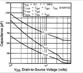
The spec sheets of many mosfets include a capacitance VS voltage graph like the one included here. In a follower application the gate and the source remain at a nearly constant voltage with respect to each other, so the Ciss and the Coss specs aren't too important. The Crss spec is the gate to drain capacitance. The drain is usually bypassed to ground through the power supply, so Crss appears directly across the output of the preceeding stage.
Yes, a tube can exhibit some voltage modulated capacitance effects. There is an "electron cloud" or "space charge" surrounding the cathode. It is more conductive than the sorrounding vacuum. With a strong negative bias the cloud will be compressed around the cathode. As the bias is reduced the cloud expands. It also becomes less dense losing conductivity. This effect can cause the grid to cathode capacitance to be modulated with signal, but the effect is far weaker than it is in a semiconductor.
Attachments
I have IRF820s set aside for this amp. They are the MOSFETs recommended in "MOSFET Follies" Trust they are OK, as that is all I have
I put a pair of IRF 820's in the amp. One blew instantly, and the other lasted until I turned up the drive.
Most mosfets have internal zener diodes to keep the gate voltage from going high enough to blow the oxide. These fets do not have the diode, so the gate got blown in both of them. It may be possible to add an external diode.
I spent all day tweaking on this amp. It positively rocks now. It is late now. so I will report further tomorrow morning.
Attachments
agent.5 said:I see that you are using "the" surplus Plitron output transformer.
I also see one of those huge ACS caps. I got 6, I'm still wondering how I'm going to safley mount them in any "regular" sized chassis.
athos56 said:
I also see one of those huge ACS caps. I got 6, I'm still wondering how I'm going to safley mount them in any "regular" sized chassis.
You just have to redefine "regular". You can mount them horizontally just like how they fitted inside the USPS box.
I see that you are using "the" surplus Plitron output transformer.
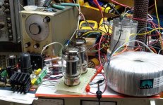
Yes, I usually perform all of my experiments that could end badly with a surplus "guitar amp OPT" that I have a bunch of. I also use a well worn pair of Chinese 6L6GC's This way I won't cry if I fry something. It also has been by standard test for years, so that I make comparisons.
I did fry one OPT too. The load resistor blew open during a maximum power test. The fire gods danced inside the OPT. That is why I now use the 500 watt load resistor standing on end behind and to the right of the ASC cap. Can't blow that one!
I spent the day tweaking and tube rolling, and last night I decided that it was time to hook up the good stuff. I made an attempt to clean things up (OK no clip leads in the signal path) and tried some better quality OPT's and tubes.
I had been saving the Plitrons for "something special". Could this be it? I had been thinking that I wanted something that could really use up some of the 400 watt at 20Hz rating that these transformers carry, but is that realistic? Would I actually use a 1KW tube amp? It would be cool, the ultimate bragging rights, but with the heat is south Florida, I couldn't turn it on for more than 5 minutes. That is about how long it would take to eat my speakers too!
I have used the Plitrons in several experiments before, but nothing really sounded good enough to build. I wired one of them into this amp and I was suitably impressed. I listened to this amp for several hours last night with everything from Dianna Krall to Metallica. These things sound good, really good. Last night convinced me to build an amp with this stuff. The reality of this is that a 75 WPC amp is more than enough and these transformers have been doing nothing useful for far too long.
For now my plan is to build an amp, maybe a quick and ugly amp, using two of these driver boards, two of the tag boards for the output tubes, the two Plitron OPT's and maybe an Antek toroid for power. I always design the power supply last.
I learned this about the Plitrons last night:
They are rated for 1250 ohms CT with 2, 4, and 8 ohm secondaries. In this configuration they claim 400 watt capability at 20 Hz.
They work very well at 2500 ohm CT with 4, 8, and 16 ohm secondaries and at 5000 ohm CT with 8, 16, and 32 ohm secondaries. The power rating with these configurations is far beyond anything that I could throw at them.
I used 6L6GC's with the transformers wired for a 5000 ohm load. Maximum power in triode mode was 40 watts. The usual 3 db frequency response plots at 1 watt are meaningless. The upper 3db point is 64 KHz. I tested frequency response at +0 -1db. The result 6.5 Hz to 44 KHz. Response over 20 Hz to 20KHz is within 0.1db!
I then tested the amp with the EH KT88's wired for a 2500 ohm load. The B+ was 450 volts and idle current was 65 mA per tube. The results are better! Response at +0 -1db, 5.1 Hz to 46.9 KHz. The upper 3db point is 66 KHz. The distortion at 60 watts and 20 Hz is 4.3 %. Output with input shorted, 0.8 mV.
Measured distortion :
2500 ohm load triode mode
THD at 1 watt 0.19%
5 watts 0.54%
10 watts 0.95%
20 watts 1.52%
40 watts 1.84%
60 watts 1.77%
70 watts 3.08%
75 watts 4.18%
78 watts 5%
90 watts 10%
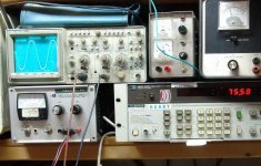
The picture shows the scope at the edge of clipping, and the power meter reading over 75 watts.
Attachments
I also see one of those huge ACS caps. I got 6, I'm still wondering how I'm going to safley mount them in any "regular" sized chassis.
I usually mount motor run caps with the band clamps made for mounting big elecrtolytic cans of similar size. That would leave a big ugly threaded stud sticking out of the top of the cap. I have 6 of these caps too. I may try to cut the stud off of one, but I doubt that would turn out good. My other thought is to look for something that would thread on to the stud that doesn't look ugly. Check out one of the stores that caters to the import car tuner crowd.
In this case I have 3 big ugly toroids to hide. The ASC cap is starting to look good!
Get yourself a nice chrome-plated grapefruit shooter for it. How about a wing nut. I've got 9 of those caps on the way. I bought 6, but then I noticed the deal was buy two and get one free...LOL.
My mind is still rather boggled by the amount of power you are getting out of a pair of 6L6 tubes. I guess I never really looked at what was possible in class B, since I've never seen it done well until now. Then again, I've never had a MOSFET in a tube amp until a few months ago....
My mind is still rather boggled by the amount of power you are getting out of a pair of 6L6 tubes. I guess I never really looked at what was possible in class B, since I've never seen it done well until now. Then again, I've never had a MOSFET in a tube amp until a few months ago....
tubelab.com said:
I put a pair of IRF 820's in the amp. One blew instantly, and the other lasted until I turned up the drive.
Most mosfets have internal zener diodes to keep the gate voltage from going high enough to blow the oxide. These fets do not have the diode, so the gate got blown in both of them. It may be possible to add an external diode.
I spent all day tweaking on this amp. It positively rocks now. It is late now. so I will report further tomorrow morning.
A few years ago, i was experimenting with the powerdrive and using IRF 820 Mosfets....
All was well, until I turned the wick up then one went short, The 811A on that half of the P-P didnt like it much--Its grid glowed a loverly brightness, hotter than the heater,-amazingly it survived!
I think what happened, was the drive voltage to the MOSFET exceeded the supply To the fet by the Gate/Source breakdown volts, and 'punched-through', killing the fet (I was using a 150V supply to the MOSFET Follower stage in that bread-board as I recall
Anyway, my 'Cure' was to add a zener, a small 250mW one between the Source and Gate. I used a 12V one, and mounted it directly on the pins of the fet.
--I used a 100K 'Gate-Stopper' and connected everything to the gate through that....
Worked well and its what I use when using MOSFETS as followers ever since.....
--Thanks George for sharing all your exploits, I always look out for your posts here, They are a great inspiration,--You'll be extracting 100 watts outta a 12AT7 next!

tubelab.com said:
I usually mount motor run caps with the band clamps made for mounting big elecrtolytic cans of similar size. That would leave a big ugly threaded stud sticking out of the top of the cap. I have 6 of these caps too. I may try to cut the stud off of one, but I doubt that would turn out good. My other thought is to look for something that would thread on to the stud that doesn't look ugly. Check out one of the stores that caters to the import car tuner crowd.
In this case I have 3 big ugly toroids to hide. The ASC cap is starting to look good!
Chrome-dome lug nuts! The inside threads can be oversize. Actually,
you can probably find chrome plated cap nuts of the proper size at
a good hardware store. Another thought was to make a cool looking
plate out of lexan or aluminum to bolt on top of these when mounted
in the usual way. This might look really cool with more than 2 caps in
a nice geometric design. Maybe you could fashion a clever "hat" for
them. A knit cap is what I always used to hide an ugly haircut ;-)
I'll bet Geoff Kait could come up with a clever lil something or other
that would improve the sound at the same time!
I just picked up a bunch of 40/600VAC CDE caps with the mounting
studs for a big voltage doubler project. I decided to build an enclosed
chassis with exposed wiring on top since I have these output tubes
with external anodes anyway. I'm just going to bolt them through
the top plate, terminals up. But, another option is to mount them
below deck horizontally, perhaps bolted through the back plate.
I would connect a bleeder resistor permanently to each one before
applying voltage to them.
Cheers,
Michael
PS Oohh, how about a toroidal terminal like on a tesla coil...
tubelab.com said:I had been saving the Plitrons for "something special". Could this be it? I had been thinking that I wanted something that could really use up some of the 400 watt at 20Hz rating that these transformers carry, but is that realistic? Would I actually use a 1KW tube amp? It would be cool, the ultimate bragging rights, but with the heat is south Florida, I couldn't turn it on for more than 5 minutes. That is about how long it would take to eat my speakers too!
Well, I think you can make a dual channel amp with switches for triode and pentode mode, high and low power. Just like a Rivera TBR-5. Put it inside a 4U (maybe 6U with the Plitron and ASC caps) chassis and tour the World with a Fender guitar.
http://www.youtube.com/watch?v=W85g0XyTqyE
was the drive voltage to the MOSFET exceeded the supply ....Anyway, my 'Cure' was to add a zener, a small 250mW one between the Source and Gate.
I think this is how I blasted the IRF820's. One of them blew when I switched ranged on the audio generator. I had found a package that originally had 5 parts in it. 3 were left. I just blew up 2 of them. I vaguely remember blasting the first two in the same manner a few years ago. That is when I started using the Toshiba parts since they have the zener diodes built into them. I would try the 820's again except I inly have one left. I will get some more and some 10 or 12 volt zeners next time I order parts. I have been using 1 K ohm gate stoppers with the Toshiba parts. So far I have killed one of them and it happened when the ground lead on my scope probe landed in a live board yesterday.
You'll be extracting 100 watts outta a 12AT7 next
Nah, 12AT7's are a useful tube. I have several hundred 12AU7's how many do I need to hook together to make 100 watts?
Well, I think you can make a dual channel amp with switches for triode and pentode mode, high and low power.
Whatever I build, its main use will be for HiFi. Arthritis and stiffnes has limited my guitar playing lately. I am still waffling about the tube and power output choices, and a few more experiments are in order, but I really liked what I heard last night, so that may be the amp design if I don't come up with something better by the time I am finished with the Tubelab SE I am building now.
I have never found a pentode amp that I really liked the sound of. I have always preferred triode for sound and UL for power. These transformers do not have UL taps, ans I am getting plenty of power in triode, so I see no reason to use pentode. I am thinking about adding a class A mode switch that will limit the power to maybe 30 WPC. I have to experiment with using a really big CCS in the cathodes of the output tubes to make the amplifier fully differential. This will force class A operation, and reduce power output, but I think that it may improve the sound. If I need more power, I can add more tubes, or use bigger tubes!
My mind is still rather boggled by the amount of power you are getting out of a pair of 6L6 tubes. I guess I never really looked at what was possible in class B, since I've never seen it done well until now.
There is no class B here. This amp runs in AB2 mode. True class B runs at zero idle current. That usually offers up tons of crossover distortion, so some idle current is used. Most conventional tubes don't do well in class B but there are tubes designed specifically for class B operation. Screen driven sweep tubes do work well in class B operation but this thread was all about class AB2, and the 6L6GC so that is where I started. I just happen to have 7 EH KT88's and 1 EH 6550 (same tube) and I like the sound of them more so I have been swapping back and forth. I have some EH EL34's too, so they will get tested sooner or later.
AB2 does allow for some added power output over what is found in AB1. This is clearly stated in the vacuum tube data books that go back to the 1930's. The problem was thay didn't have good drivers that could work into the extreme changes in grid impedance seen in AB2 mode with low distortion in the 1930's.
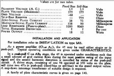
Check out the screen shot from the data sheet for the RCA 45 tube. Yes, a pair of those little guys were rated to put out 18 watts in AB2. No, I haven't tried it yet. RCA rates the 807 which is a 6L6GB at up to 120 watts for a pair in AB2.
Attachments
tubelab.com said:I have several hundred 12AU7's how many do I need to hook together to make 100 watts?
18 would do it, but 20 would be safer. You could do mono-blocks, and call them the Tubelab Twenties.
tubelab.com said:I have never found a pentode amp that I really liked the sound of.
My old PP EL84 pentode amp sounds pretty good for a simple circuit. Not quite as good in the bass region as big trioded tubes, the OPT's are rather small.
Jeff
I'd hate to try it with a 45...but I have like 10 pairs now, so....
I have a few 45's that I have collected over the years. Most are well used and not "grade A" quality. I did some experimenting with A2 operation in the Tubelab SE and found that many tubes that work fine in a low powered amp simply do not have enough emission left in their old filaments to take advantage of A2 or AB2 mode. If every electron leaving the filament makes it to the plate with a slightly negative grid voltage pushing the grid positive will not increase plate current. In fact the plate current may actually decrease because some of the electrons were diverted to the grid. Measurements on several old 45's seem to support this theory.
I have found that tubes with plenty of reserve emission capability make good canidates for A2 or AB2 operation. There can be too much of a good thing though. I have yet to get good AB2 operation with some of the monster sweep tubes like the 6LW6. The emission capability of the cathode is so great that the control grid will draw several hundred milliamps with a small positive voltage. This lead to a tube arc yesterday which is a very bad thing when you have that monster ASC cap feeding the fire.
My old PP EL84 pentode amp sounds pretty good for a simple circuit. Not quite as good in the bass region as big trioded tubes, the OPT's are rather small.
Since it was an easy experiment I connected the KT88's in pentode mode. As expected I got more power. Full tilt with the power supply dialed up tp 475 volts is 130+ watts. I only had one power supply accessible at the time so the screens are connected to 475 volts as well. I noticed some screen glow whenever the power meter was above 100 watts. I connected the DVD player and speakers and applied some Depeche Mode. The bass was far "looser" than triode mode but could probably be cleaned up with some feedback. Could enough feedback be applied to clean up the bass without sucking the life out of the sound? I don't know yet.
The distortion measurements were quite a bit higher than triode mode too:
2500 ohm load pentode mode
THD at 1 watt 0.50%
5 watts 1.13%
10 watts 1.71%
20 watts 2.60%
40 watts 3.95%
60 watts 4.7%
80 watts 4.97%
100 watts 4.41%
120 watts 4.03%
130 watts 5%
18 would do it, but 20 would be safer.
OK, would that sound as bad as one big 12AU7 or 20 times worse? Seriously, it has been stated multiple times by several people on this forum that all 12AU7's suck. I have not yet formed my own opinion on that, but it's for a different thread at a different time. When I have time I will have no problem melting a few of them in the name of science.
On the other hand most agree that the 6SN7 is a good sounding tube. The tubes in this amp sure do sound nice. Could it be that one with the red base that is giving this amp its magic sound?
tubelab.com said:Could enough feedback be applied to clean up the bass without sucking the life out of the sound? I don't know yet.
My little amp has local feedback only.
tubelab.com said:Seriously, it has been stated multiple times by several people on this forum that all 12AU7's suck.
And some other forums as well. Some of them really do stink, but some don't sound too bad.
Jeff
- Status
- This old topic is closed. If you want to reopen this topic, contact a moderator using the "Report Post" button.
- Home
- Amplifiers
- Tubes / Valves
- 6L6GC AB2 Amp