With reasonable power supply voltage, its possible to run your
chosen tubes to full power without need for driving G1 into A2.
Not sure what A2 here buys you, but an added complication?
I don't think A2 is necessarily a bad thing for Triodes and some
Pentodes. Especially when run at lower than "normal" voltage,
and you might want more current without increasing voltage.
But I'm not too sure its a great thing for Beam Power tubes?
Alignment of G2 to the shadow of positive G1, may mean G2
now sits where G1 could FOCUS those beams directly onto it.
I don't know if it works like that IRL, it just worries me...
Don't imagine a problem if you space charge the tube with a
positive G1. As long as G2 remains always negative, as this
mode could repel the offending focused beams safely away.
1W of acceleration at G1 can effectively replace several watts
at G2. By effective, I mean for the same plate current.
Do real space charge tetrodes deliberately misalign G2? With
an intent that G1's shadow will focus differently when driven
positive?
I think I'd rather have an unaligned Pentode than a Beamer
if both are grids are intentionally going to be driven positive,
even if only at the music peaks.
6L6GC's give plenty of power in AB1, because you can crank the VG2...
If you're bent on AB2, I'd go with 807's... at least they look nice")
They're basically a 6L6GB, higher Va rating, nice ST bottle, cheap, even US ones... the war office had them churning out tons of them during WWII... korea too, and some antiques were probably still running 'em in vietnam.
They don't need too much drive.. AB2 something like
Va = 600
Vg2 = 300
Rl = 6k
should do ~80W at ~3% THD without any NFB, iirc... which you can add of course...
If you're bent on AB2, I'd go with 807's... at least they look nice
They're basically a 6L6GB, higher Va rating, nice ST bottle, cheap, even US ones... the war office had them churning out tons of them during WWII... korea too, and some antiques were probably still running 'em in vietnam.
An externally hosted image should be here but it was not working when we last tested it.
They don't need too much drive.. AB2 something like
Va = 600
Vg2 = 300
Rl = 6k
should do ~80W at ~3% THD without any NFB, iirc... which you can add of course...
Man oh man, does the Tamura F-684 look SWEET. That "iron" would KILL in an all out "El Cheapo Grande".  I am positively GREEN with envy!
Let's stick with the 6L6GC. A 450 V. B+ rail will be very comfortable for UL mode "finals". 100 Ohm Carbon film resistors right at the g2 socket lugs do double duty as stoppers and current limiters.
I am positively GREEN with envy! Let's stick with the 6L6GC. A 450 V. B+ rail will be very comfortable for UL mode "finals". 100 Ohm Carbon film resistors right at the g2 socket lugs do double duty as stoppers and current limiters.
McIntosh ran their amps in AB2 but avoided crossover distortion through the use of a very complex bifiliar wound transformer...
This didn't have really anything to do with the amp being AB2 or AB1 but that it was a unity coupled design. Because it was unity coupled, they were able to run much lower quiescent currents without too much crossover distortion.
Class AB2 is a lot closer to class B, especially on strong peaks, then it is to A.
Any amp (AB1 or AB2) is closer to class B when one tube cuts off. In fact, it has actually arrived there at that moment.
clipping is also greater in class AB2 operation then class AB
Sorry, a well designed AB2 driver softens clipping at the onset of grid current substantially and eliminates blocking distortion.
I have a KT88 amp on my bench right now that has a source follower directly coupled to the grid. It is triode connected with a B+ of 450V and a quiescent current of 50mA. I currently have 1k grid stoppers on the KT88s. All I need to do is remove the 1k resistor and bridge it with a wire and I have an AB2 amp. Am I to understand that at the moment that I make the swap I will suddenly start generating crossover distortion? Why would that happen? I haven't altered the quiescent operating point at all, just increased headroom.
Actually, I've listened to music with this amp at full throttle and it sounds surprisingly good even when clipping grossly. Not good, mind you, but not nearly as bad as the scope traces seemed to indicate it should.
Just look at 6l6 positive grid curves. There is nothing ugly there. It is just harder to get there.
SY said:
Nowadays, even us old die-hard tube guys have to admit that a source follower does better. I've been using them in AB2 drive without seeing anything like crossover distortion. And likewise, I've used them in screen drive, which is even more demanding of the driver.
The advantage of a follower over a transformer, besides bandwidth and lower source impedance and distortion is that it's not a stepdown. This reduces the distortion of the driving stage. It's a win-win.
Sy, and all the others: Thanks for the clarifications on this topic.
So please tell, what are the design considerations when dropping in a MOSFET source follower before the output tube? What parameter minimums and maximums should I be looking for?
Also, although I realize it's not a true 6L6, but would a source follower work in a Williamson topology?
Thanks!!
Class AB2 is a lot closer to class B
In what way? Let's consider a 6L6. Looking at the GE datasheet, for AB1, 360V on the plate, 270V on the screen, the plate to plate load is 3k8, idle current is 88mA. For AB2, same voltages, same plate load, the idle current is... 88mA. So the cutoff of each side is at the same point, regardless of whether or not you take the already-turned-on side into grid current on peaks. The only difference is the max current, which is irrelevant to anything involving crossover or notch distortion.
Rob, I just use an IRF820 with a +/-200V supply in a plain vanilla source follower configuration. 10mA idle current. I've tried fancier circuits like cascodes, but found no real advantage. The device that Eli suggested should work even better, I just haven't used it, and to be honest, the source follower isn't the weak link in my amp anyway.
Wow!
I am glad that there is so much interest being generated! I must admit, much is going over my head...
Yes Eli, those transformers look sweet! I picked them up one day when my self control was not that great Since that happened, I have purchased an apartment with my partner and now have a mortgage... The other thing is that now I have to be a little 'low key' with my purchases. This is why I want to make sure I have a pretty good idea what spec we are talking about so I can start looking at sourcing the power iron. With economies around the world going down, Australian dollar fluctuating, the industry I am in being reliant on discretionary spending etc I have to be a little more cautious and careful with spending. Also have to answer to my 'better half' now
So, are we talking el-cheapo grande, or as discussed above with AT7 driver, ECC99 LTP and mosfet source follower (or are they the same thing!).
This is getting interesting! looking forward to getting in to the books and getting the soldering iron and scope out of storage!
Cheers,
Chris
I am glad that there is so much interest being generated! I must admit, much is going over my head...
Yes Eli, those transformers look sweet! I picked them up one day when my self control was not that great
Since that happened, I have purchased an apartment with my partner and now have a mortgage... The other thing is that now I have to be a little 'low key' with my purchases. This is why I want to make sure I have a pretty good idea what spec we are talking about so I can start looking at sourcing the power iron. With economies around the world going down, Australian dollar fluctuating, the industry I am in being reliant on discretionary spending etc I have to be a little more cautious and careful with spending. Also have to answer to my 'better half' now So, are we talking el-cheapo grande, or as discussed above with AT7 driver, ECC99 LTP and mosfet source follower (or are they the same thing!).
This is getting interesting! looking forward to getting in to the books and getting the soldering iron and scope out of storage!
Cheers,
Chris
SpreadSpectrum said:
Because it was unity coupled, they were able to run much lower quiescent currents without too much crossover distortion.
Yes, that was exactky my point. Glad you agree.
clipping is also greater in class AB2 operation then class AB
Sorry, a well designed AB2 driver softens clipping at the onset of grid current substantially and eliminates blocking distortion.
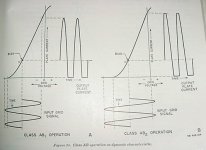
I was refering to clipping originating at the output stage. Not clipping caused by the driver. Please see the diagram below.
I currently have 1k grid stoppers on the KT88s. All I need to do is remove the 1k resistor and bridge it with a wire and I have an AB2 amp.
At first I was scratching my head over this. How could simply bridging the stoppers move the output class to AB2 without changing the quiescent operating point? Then it occurred to me that perhaps we are talking about two different things. Correct me if I'm wrong here. You're referring to allowing AB2 operation (grid current) to happen in an AB biased stage by way of a strong supporting driver stage. I was referring to a leanly biased output stage to allow higher plate efficiency. This was also called AB2 since it was closer to B. Since I learned this stuff many years ago I may have melded the terms somewhat.
Victor
Attachments
Victor,
I think we are speaking the same language now.
Am I mistaken in thinking that given a perfect driver, clipping shouldn't occur until Vg = Vp, which is when the grid would swallow up all electrons from the cathode? Is that what the diagram is depicting?
Edit:
Sorry, just looked at the figure again and it seems that it is clipping at Vg = 0. Maybe this guy needs a source follower.
I think we are speaking the same language now.
I was refering to clipping originating at the output stage. Not clipping caused by the driver. Please see the diagram below.
Am I mistaken in thinking that given a perfect driver, clipping shouldn't occur until Vg = Vp, which is when the grid would swallow up all electrons from the cathode? Is that what the diagram is depicting?
Edit:
Sorry, just looked at the figure again and it seems that it is clipping at Vg = 0. Maybe this guy needs a source follower.
SpreadSpectrum said:Am I mistaken in thinking that given a perfect driver, clipping shouldn't occur until Vg = Vp, which is when the grid would swallow up all electrons from the cathode? Is that what the diagram is depicting?
Look at 12K5: Characterized G1 and Plate both at Positive 12.6V!
G2 at Negative 2 Volts! Plenty of electrons still reaching the plate...
My point is that G1 here didn't suddenly become a solid plate and
arbitrarily swallow up all the electrons. Its still mostly an empty grid.
I suppose if a tube were severely emission limited, there could be
an issue. Perhaps exceeding what the cathode coating can emit.
SY said:Curious about where the diagram is from. It appears to be incorrect.
It's from a U.S. Army techicnal manual. After some thought and study on this, I too am beginning to question it's accuracy. I believe that when driving a tube into gird current it is basically being overdriven to some extent. Although viable, it's range must be limited by the tube itself or it's working environment. But this text was from 1952. It may be illustrative of the state of the art back then (no fets
), who knows.Victor
Attachments
My point is that G1 here didn't suddenly become a solid plate and arbitrarily swallow up all the electrons. Its still mostly an empty grid.
I guess now that I think about it, I got the idea that plate voltage wouldn't dip below grid voltage from the 211 data sheet.
If the tube is capable of it, why did RCA stop the curves at Vg = Vp? Is it just that it is harmful to the tube maybe?
weinstro said:So where does this leave us now?
What about the phase splitter? Is it better to stick with the type on the Mullard 5-20, or something with equal loads in the plate and cathodes such as ok the Williamson or Red Light District?
Thanks!
Rob,
Williamson topology is stable, ONLY if absolutely top notch O/P "iron" is employed. Can you say phase shift oscillator?
"Concertina" phase splitters are limited in the voltage they can swing. So, Fisher/Dyna style circuitry is out. Mullard style circuitry of a voltage amplifier DC coupled to a LTP provides the requisite voltage swing, while dodging the phase shift instability issue.Please observe that adding MOSFET voltage followers that are DC coupled to the O/P tube control grids does not increase the cap. count in the signal path. AAMOF, because FETs are very tolerant of large resistances in their gate circuitry, keeping the "corner" frequency of the high pass filter that's present sufficiently low is not problematic. PTFE dielectric coupling caps. become fiscally reasonable.
chrish said:In this thread Amp design suggestions Eli was suggesting a 6L6 AB2 design based on Mullard 5-20 topology with 12AT7 front end and ECC99 LTP and Mosfet source followers. Respecting the original thread, Eli asked to start this new one.
If you're going to do that, then go to Retrovox and download the application reports for the 6L6 and 807. These types are nearly identical (807 can operate at higher plate voltages since it has a top cap connection).
Having done a design with the 807, you're going to need some local feedback to tame its otherwise nasty open loop performance as it likes to make higher order harmonics, more so than for types like the 6V6.
As for going Class AB2, you can get quite an increase in output. If you're going the route, source follower drivers are the best way to go. You can avoid a lot of X-over if you don't go too close to Class B operation, which is just never done where you want any kind of good sonic performance. Class B is usually reserved for RF where distortion doesn't matter since you have tuners and/or BPFs to reject it, or high powered modulators and PA systems where sonics aren't as important as efficiency.
Having done a design with the 807, you're going to need some local feedback to tame its otherwise nasty open loop performance as it likes to make higher order harmonics, more so than for types like the 6V6.
Miles,
Thanks for speaking up. Chris has yummy looking Tamura O/P "iron" that can handle 30 W. As of now, the plan is 6L6GCs in UL mode and the B+ rail is "450" V. For UL mode, the extra voltage handling capability of the 807 anode does not enter the picture, unless a separate screen grid tertiary winding is available.
Given the 30 W. limit of the O/P trafos, a set of operating conditions with some positive g1 current and relatively close to Class "A", with both "finals" conducting most of the time, seems distinctly possible.
Thanks so much everyone for the interest and input so far. I find myself in your debt regarding the amount of knowledge and effort you all go to to guide the less knowledgeable (but enthusiastic!) amongst us.
This is all sounding very interesting. To recap a little, I have the output iron, but not the power supply iron. So, we are looking at about 450V B+. I guess that is going to work out to about 350-0-350 volts for the transformer if valve rectified, about 320-0-320 if silicone rectified. At least 200mA current each for the mono blocks.
What about for the B-? I am guessing separate transformer for this under the chassis?
Not in a big rush, we can work out fine detail of the design as we progress, but would like to be able to keep my eye out for iron on my travels.
Last university assignment for the year due in tomorrow, then I will be able to do a little research and ask some more intelligent questions.
Once again, thanks for the help so far!
Chris
- Status
- This old topic is closed. If you want to reopen this topic, contact a moderator using the "Report Post" button.
- Home
- Amplifiers
- Tubes / Valves
- 6L6GC AB2 Amp