George, isn't it better to use less than 470k bias resistors, since the old manuals state 100k in fixed bias for KT-88 as an example? It would fatten up the couplers before the Mosfet buffers a bit though. Maybe 220k is good for modern production beam tetrodes?
Also, how many Watt you get in triode mode before clip for a KT-88 pair with 400V B+ and powerdrive?
Also, how many Watt you get in triode mode before clip for a KT-88 pair with 400V B+ and powerdrive?
George, isn't it better to use less than 470k bias resistors, since the old manuals state 100k in fixed bias for KT-88 as an example?
The 470K sets the bias on a mosfet,which then offers the grid of the power tube a much lower impedance. It is less than 10 K in this design.
Also, how many Watt you get in triode mode before clip for a KT-88 pair with 400V B+ and powerdrive?
No measurements on the KT88 yet.
Crap that is a bad situation for everyone involved, including the neighbors.
The only cool thing is that you did what I would have done, get a bead on the whole situation and take pictures... Of course I would have forced everyone else in my family down to the basement first.
Hmm, you don't have basements in FLA do you? But then again, we'd probably never survive a hurricane up here...
Ok - this is totally off topic and I apologize in advance. But Friday I was visiting a friend of mine when we noticed a fire in a nearby clearing. Although with all the rain these days you could probably call it more of a budding forest. In any case it was odd enough that I had to go investigate. Turned out someone had set 2 Dell cpu's on fire!
There were no hard drives or memory, so why would they do that? In any case, only armed with my feet, I managed to put one of them out. The second one was a bit more reluctant - apparently CDROM drives burn pretty well.
So we called the locals. Oh, my - call the drama squad. Fire, police and local volunteers showed up to put out a CDROM fire! One of the police officers told me not to touch it because I shouldn't get my finger prints on it.... Yes obviously CSI would be along soon to investigate")
Gotta love small towns.
The only cool thing is that you did what I would have done, get a bead on the whole situation and take pictures... Of course I would have forced everyone else in my family down to the basement first.
Hmm, you don't have basements in FLA do you? But then again, we'd probably never survive a hurricane up here...
Ok - this is totally off topic and I apologize in advance. But Friday I was visiting a friend of mine when we noticed a fire in a nearby clearing. Although with all the rain these days you could probably call it more of a budding forest. In any case it was odd enough that I had to go investigate. Turned out someone had set 2 Dell cpu's on fire!
There were no hard drives or memory, so why would they do that? In any case, only armed with my feet, I managed to put one of them out. The second one was a bit more reluctant - apparently CDROM drives burn pretty well.
So we called the locals. Oh, my - call the drama squad. Fire, police and local volunteers showed up to put out a CDROM fire! One of the police officers told me not to touch it because I shouldn't get my finger prints on it.... Yes obviously CSI would be along soon to investigate
Gotta love small towns.
chrish said:So AB1 UL 6L6 output, IFRBC20 mosfet follower, ECC99 LTP, driven by 12AT7? Will have to wait till I get home to consult Morgan as I am a bit clueless as to how to set this all up
The sound is all in the details. I'm building a guitar amp with almost identical specs. 6L6 in push/pull. LTP,. using 12AX, not the AT. The difference between HI-Fi and a musical instrument amp that is capable of intentional distortion is what value resistors and caps you choose and the gain of each stage.
It would be a problem if there was a CCS instead of the 10k Rload? Offering a high impedance load to the source follower, the 470k would dominate?
The 470K is on the gate side of a mosfet. It can not come into play here. PowerDrive like any follower provides non symetrical drive capability. In this case it is exactly what is needed.
The reason that there is a maximum resistance spec on the grid of most tubes (especially power tubes) is grid current.
If the tube was perfect the grid would collect a few electrons that just happen to land there. This would result in the grid receiving a negative charge. If there was no path for these electrons to flow the grid voltage would go negative enough to cutoff the tube. This fact was exploited in the early days of the vacuum tube era. it was known as grid leak bias. A high value (1 meg or more) resistor was used to leak off just enough electrons to establish proper bias.
We know that all tubes are not perfect. The grid is close to the cathode. It gets hot. Hot enough to emit some electrons which travel to the plate or screen. There is a residual gas inside the tube, and some of these "gas" molecules will ionize and form a conductive path from the grid to the plate or screen.
We now see that there is one action attempting to make the grid negative, and two attempting to make it positive. Without intervention it is impossible to specify the unbiased behavior of a tube. Fortunately these are all weak actions resulting in a few microamps of grid current. The manufacturer specified a maximum value of grid circuit resistance to be sure that any uncontrolled grid current would result in a small change in grid voltage. The maximum resistance value would still apply in the mosfet follower case. If the 10K resistor was increased to 1 meg there could still be a runaway problem if the grid attempted to go positive. Fortunately we don't build too many followers with 1 meg loads.
True the CCS would offer a high dynamic impedance. It would still be capable of sinking 5 to 10 mA (or more) which would easilly swamp a few microamps of grid current. I have used CCS loads in this position without issue, and they may offer a slight improvement, but I have not found it worth the added complexity.
As I stated before the follower is an asymetrical drive source. It can sink only as much current as the CCS or 10K resistor to the negative supply can pull. Fortunately the driver has two tasks as it tries to pull the output tubes grid negative. It must overcome the grid current (microamps) and it must discharge the miller capacitance of the output tube quickly enough to avoid slew rate limiting. 5 to 10 mA is overkill!
The story is different in the positive going direction. As the output tubes grid starts to approach zero it will draw current. This current can be 10's of mA for most tubes and hundreds of mA for big transmitting tubes like the 833A. This current is limited only by the RDSon of the mosfet (a few ohms) and the source impedance of the positive supply (hopefully below 1 ohm). This allows a low distortion drive signal to force the output tube's grid exactly where the driver tells it.
Some modern tubes use a gold plated control grid to help reduce grid current. The plating is often only a few molecules thick. It has been suggested that these tubes do not like operation with heavy or continuous grid current. Some means of limiting the grid current is suggested with such tubes.
A few more details:
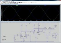
The picture of clipping shown above was taken with music (Dire Straits) playing through speakers.
I worked on the circuit as shown in chrish's last PDF schematic. I could not get the direct coupled CCS loaded circuit to work repeatably with a wide variety of 6SN7's. Good DC and AC balance is not simultaneously possible with all tubes. A slight drift in the input tube can lead to seroius shifts in the balance at the output. It is possible to get the whole thing oscillating in a maner that resembled a flip flop circuit. I made the following two changes.
1) I added resistors across the CCS's in the plates of the output stages. This adds some slope to the load line and removes the tendency to act like a flip flop. I plan to experiment further to see if the CCS's may not even be needed here.
2) I added an RC snubber across the tail resistor in the output stage. This eliminated the tendency to oscillate when driven into heavy clipping. More experimentation is needed here also.
Notes:
Even with these changes there is sufficient gain to drive the trioded KT88's to clipping with the volume control at half way up. This is using a CD player and speakers. No measurements were made.
I have not tried any global feedback, nor do I believe any is needed with triode mode and KT88's. The bass is very solid and strong.
I put a scope probe on the grid of the KT88 and saw that the grid was swinging from +25 volts to -100. This is the supply rail voltages for the mosfet driver. This leads me to believe that more power would be available with higher rail voltages. +25 volts is the limit of the power supply that I am using, and -105 is a common VR tube voltage, which was one of chrish's design goals. He did not plan to use KT88's but I couldn't resist it and I like the sound of them enough to explore them further.
All testing was done with the B+ supply set at 400 volts, which again was one of chrish's design goals. You know that I will explore that area to the right of that number on the power supply meter face eventually.
Sherri comes home tomorrow for 20 days, so I won't be doing much testing for a while.
Chrish:
Based on these experiments I would plan on swapping your supply voltages for the mosfet buffer. Make the positive supply +75 volts and the negative supply -105 volts. Leave room for resistors (3 to 5 watts) across the CCS's (or possibly in place of them) in the output stage, and possibly for a resistor and capacitor in series across the tail resistor.
I have done a pretty good job of destroying the PC board that I made for this experiment. Fortunately, I made two, but those experiments will have to wait.
Wow!
I have been away with work for a few days. Great to see the results of your experiments George! Design voltage was 400v as several data sheets listed this as one of the ideal operating points for 6L6 and 7591 (the types I will be using). My power transformers are 300BX, 400-0-400, so getting more voltage is no problem. Limit is 450v for 7591, so I could shoot for 450v no problem.
As for the other suggestions, I will incorporate in to my design as soon as able. Away in a couple of days again and should have some time off in the hotel to redraw the schematic.
Thanks George!
why not use a higher valued resistor to bias the MOSFET? I use 1M without problems. Is there a reason not to?
1M would be fine. 470K was the first large value resistor I came to when I started looking for parts. If the resistor gets too big you can see the effects from imperfect mosfets like gate leakage. The bias adjustment gets sluggish because of the RC constant formed by the 1M resistor and the coupling cap.
With power drive we always gain in power and THD even if the full swing to B+ could be exploited even before adding powerdrive?
PowerDrive does two things:
It eliminates blocking distortion caused whenever there is a capacitor tied to the output tubes grid and a fairly large resistor from the grid to ground (or the bias supply). This is an advantage on any output tube that may ever possibly be overdriven even briefly.
It also allows the grid to be driven positive. This may or may not be an advantage depending on the output tube being used and how it is biased. Most triodes and many triode strapped pentodes can only pull the plate down to +50 to +100 volts. A2 operation reduces this voltage and raises the peak current capability of the tube provided the cathode is capable of supporting the increased current. Some tubes can not support the current, and some will be non linear with a positive grid voltage. The power improvement varies from tube to tube and with bias conditions. Experiments with old used 45's reveal that the emission capability of the filament greatly influences the amount of improvement seen with A2.
Design voltage was 400v as several data sheets listed this as one of the ideal operating points for 6L6 and 7591 (the types I will be using).
If I remember correctly your chosen OPT's were only capable of 25 to 30 watts, so 400 volts may be a reasonable choice. I have a pair of UTC LS-57's somewhere, but I haven't found them yet. They have similar power ratings.
I want to build something that uses them, one of my P-P driver boards (I have 4 different ones now) and a power transformer from my collection (I have plenty to choose from). The choice of output tube is really up in the air and varies from 45's (the book says a pair will make 19 watts in AB2) to KT88's. 6L6GC's may be considered since I have some of them. I don't have any 7591's. My plans are to make a few amplifiers without spending any money. I'll then pick one to keep and sell the others. In the process I will develop a couple of good P-P driver boards and maybe a multi tubed output board for high power amps.
Lots of great experimenting and development work George! I hope there are others out there interested too!
Have taken your suggestions and modified the schematic accordingly.
Your suggestion regarding swapping the voltage supplies for the +/- to the MOSFETs had me look again at my supply transformer calculations. I putzed them up! The small transformers I purchased will not be adequate for the job. They are limited to 1A on the output, and driving the 9.5 output with 5 volts limits me to 40mA. Not really good enough. I think I will use a 50VA 9+9:240V toroid (much the same price and size as 30VA) connected to the two 5V in series. This will mean that the limiting factor will be the 1.2A on the 5V secondaries of the power transformer. If there is a little more current drawn, neither the power transformer or the torroid is going to saturate. Should be good for 90-100mA with no trouble.
Have inserted coupling caps between the two driver stages. Have biased the second stage at around -8V (looked good on the curves for 7-8mA) with a 560R resistor. 1M grid leak resistors re-inserted due capacitor coupling.
Placed the resistor across the CCS feeding the second stage. No idea as to value for this however. Same for value of resistor and cap across the cathode resistor.
No rush with the experiments George. I am half way through a guitar amp with my son (my first guitar amp). He is enjoying building it with me. Also, busy with work the next couple of weeks, then have to move house due relationship breakdown I will need this project after the move to keep my spirits up I think
Anyway, I am glad that the experiments so far appear to have been quite successful. Oh, received my digikey order today, so have the parts needed. Minor design changes will not be a problem, it is things like those 10M45s that are hard to get hold of down here (I got 20 of them for future experiments and projects).
Once again, thanks for the assistance, education and entertainment!
Regards,
Chris
Oh, the attached pdf looks small when opened, but it appears to zoom in OK with plenty of detail (on my Mac at least). Let me know if it is not legible...
Have taken your suggestions and modified the schematic accordingly.
Your suggestion regarding swapping the voltage supplies for the +/- to the MOSFETs had me look again at my supply transformer calculations. I putzed them up! The small transformers I purchased will not be adequate for the job. They are limited to 1A on the output, and driving the 9.5 output with 5 volts limits me to 40mA. Not really good enough. I think I will use a 50VA 9+9:240V toroid (much the same price and size as 30VA) connected to the two 5V in series. This will mean that the limiting factor will be the 1.2A on the 5V secondaries of the power transformer. If there is a little more current drawn, neither the power transformer or the torroid is going to saturate. Should be good for 90-100mA with no trouble.
Have inserted coupling caps between the two driver stages. Have biased the second stage at around -8V (looked good on the curves for 7-8mA) with a 560R resistor. 1M grid leak resistors re-inserted due capacitor coupling.
Placed the resistor across the CCS feeding the second stage. No idea as to value for this however. Same for value of resistor and cap across the cathode resistor.
No rush with the experiments George. I am half way through a guitar amp with my son (my first guitar amp). He is enjoying building it with me. Also, busy with work the next couple of weeks, then have to move house due relationship breakdown
I will need this project after the move to keep my spirits up I think Anyway, I am glad that the experiments so far appear to have been quite successful. Oh, received my digikey order today, so have the parts needed. Minor design changes will not be a problem, it is things like those 10M45s that are hard to get hold of down here (I got 20 of them for future experiments and projects).
Once again, thanks for the assistance, education and entertainment!
Regards,
Chris
Oh, the attached pdf looks small when opened, but it appears to zoom in OK with plenty of detail (on my Mac at least). Let me know if it is not legible...
Attachments
Let me know if it is not legible...
Looks fine on the XP machine at work. We will see if Vista can screw it up at home but it's been relatively benign so far.
I see one major OOPS. You can not run two bridges off of one transformer configured in the manner that you have them. It presents a short across the transformer through two diodes. Follow the electricity from the bottom of the winding up through the diode closest to the D8 label into ground, out of ground on the top bridge through the upper left diode and right back to the top of the transformer winding. This will make the transformer verry unhappy.
Have inserted coupling caps between the two driver stages. Have biased the second stage at around -8V (looked good on the curves for 7-8mA) with a 560R resistor. 1M grid leak resistors re-inserted due capacitor coupling.
This is a conservative approach that I have used in previous designs. It should be noted that too many capacitors in the audio path can (and usually will) make the amplifier unstable if a generous amount of global negative feedback is applied. Each capacitor introduces some phase shift and so does the output transformer. If the phase shifts add up to 180 degrees at some frequency where the total amp gain is greater than one you have met the criteria for building an oscillator! At some phase shift less than 180 degrees the amp will become unstable. This is covered in great detail in Morgan Jones Valve Amplifiers books, and in many other books including all of that over mathified stuff I was supposed to understand in college.
For this reason I am committed to making the driver board work with only one cap in the signal path. The current design works quite well, but it does take too much tweaking to make it work right. Most of what I have done so far are repeat's of the experiments I did nearly 10 years ago during the design of the 300Beast. I understand things a lot better now, and things like 450 volt CCS chips weren't available then. I have many more experiments to try.
I think that I am going to switch back to the universal driver board for some of those experiments because it is....uh...universal. I can try putting the CCS chip in the cathodes without hacking anything up.
I plan on coming away from these experiments with one or two new boards to put on my web site, so I will try just about every possible combination of tubes and parts until I get something I like.
Thanks George!
I was doing this stuff VERY late last night. While doing it I was thinking "hey, if I can run +/- supplies from the one transformer winding like this, why do SS amps have two secondary windings?" You have provided the answer!
The torroids available here only appear to have a single 240V primary. Off to Mumbai via Singapore tomorrow, so will look for something with two primaries in Singapore...
Like I said, happy to follow the experiments! Nothing is built yet and not likely to start for a month or two at least for the reasons above
Regards,
Chris
OK, spoke a little too soon about the transformers...
I have found this PCB mounted toroidal transformer that has two 9V secondaries and two 120 volt primaries rated at 30VA. That should be good for over 200mA output without saturation. Limiting factor will be the 2 x 5V heater supplies in series powering it. They are limited to 1.2A (making 90mA 180V on the output). My thinking is that if the current exceeds 1.2A from the heater supply momentarily, it is a real problem as it will not saturate the power transformer (total current draw is well below specification).
I have found this PCB mounted toroidal transformer that has two 9V secondaries and two 120 volt primaries rated at 30VA. That should be good for over 200mA output without saturation. Limiting factor will be the 2 x 5V heater supplies in series powering it. They are limited to 1.2A (making 90mA 180V on the output). My thinking is that if the current exceeds 1.2A from the heater supply momentarily, it is a real problem as it will not saturate the power transformer (total current draw is well below specification).
I have found this PCB mounted toroidal transformer that has two 9V secondaries
Those kinda look like these:
http://search.digikey.com/scripts/DkSearch/dksus.dll?Detail&name=TE70071-ND
I bought one of these several years ago (a lot cheaper then) to try as a P-P OPT. It worked, but not very well. I am sure that it is still around here somewhere. If I can find it I will hook it up and see what it will do.
Off to Mumbai via Singapore tomorrow
I think these transformers were "Made in India".
When I went to Singapore (20+ years ago) there was a place called peoples park. It was a long walk from the end of the MRT, but there were dozens of shops where electronic items could be found. Not sure if it still exists.
Yes, looks very similar... I think it should work OK. In Singapore I go to "Sim Lim Tower". Full of electronics stuff, but not much in the way of tube stuff. Close by in the "Burlington Centre" there are two shops that sell tube stuff, just behind "Fatties" restaurant (a long time favorite of airline crew).
As for getting stuff in India, not too sure about that. It is difficult enough just getting from the hotel to the centre of town, especially in the Monsoon!
Cheers,
Chris
As for getting stuff in India, not too sure about that. It is difficult enough just getting from the hotel to the centre of town, especially in the Monsoon!
Cheers,
Chris
I was sitting in a boring meeting at work yesterday so I grabbed someones laptop and decided to design a driver board. Until tonight it only exixted in the mind of the simulator. Tonight I built the driver part of it and it looks like a winner.
It is set up for 400 volts of B+, -105 volts of negative voltage, and 25 volts for the drains of the mosfets.
This design is fully differential and DC coupled all the way through, Just ignore that mosfet output stage, thats for another project.
It is set up for 400 volts of B+, -105 volts of negative voltage, and 25 volts for the drains of the mosfets.
This design is fully differential and DC coupled all the way through, Just ignore that mosfet output stage, thats for another project.
Attachments
Interested to see how it works in real life!
The driver section is alive and running. I hacked up my dual 6SN7 driver board to match the above schematic. I put in the component values from the simulation. I used 10M45's for the CCS's which need a negative supply so they are wired to -105 volts. I turned on the power and applied a signal and it was alive without any adjustment. This simulation stuff actually works sometimes. I was getting about 150 volts peak to peak out of the board with a 400 volt supply and the output cleanly rose as I cranked up the supply voltage and drive. This design is far more stable than the one with the CCS's in the plate circuit. In fact no instability was noted despite turning the knobs on all the power supplies and the audio oscillator.
If I have time I will hook up some output tubes this weekend.
The complete circuit shown is another one of my wild ideas. It is a completely DC coupled class A, fully differential amplifier. I have another simulation that uses vacuum tubes in the output stage. I plan to test these sometime soon.
The simulator will not predict the success of a novel idea. I have seen several circuits that simulate very well but just smoke when built in real life. It does however do a fair job at predicting failure. If the simulator shows that something won't work, it usually won't. It saves me the time it would take to build some of my less than brilliant designs.
- Status
- This old topic is closed. If you want to reopen this topic, contact a moderator using the "Report Post" button.
- Home
- Amplifiers
- Tubes / Valves
- 6L6GC AB2 Amp