The LTP first input stage has a CCS on the tail. I understand that this makes the load line horizontal at the current set by the CCS over all plate voltages.
A CCS instead of a plate load resistor (like the second stage) does indeed make a horizontal load line. This means that the second stage will have a gain very near 20. The CCS in the tail works more like an unbypassed cathode resistor. The first stage will have a gain of about 10, maybe less. The total gain of the driver should be 140 to 200. This should crank the 7591's and I think that the 6L6's will be happy too, because I find that you will need more drive to wake them up in triode mode, but you will find that you need less feedback with triodes too.
The cathode will need to be positive with respect to the grid, but how do I work out what this is? The only component is the 10M45 and it's adjustment resistor and stopper resistor. How many volts are dropped across this?
A CCS will drop whatever voltage it needs to force the desired current. This makes things much easier than it looks. As you pointed out the cathode will be a few volts positive with respect to the grid. The grid is at zero volts since it draws (theoretically) no current and there is a resistor to ground. So the cathode will be at a small positive voltage (3 to 8 volts). I have verified that you can indeed turn the power supply from -25 to - 400 volts, the cathode voltage doesn't change.
If you have access to a scope, the best way to set this up is to set the CCS to the desired current, drive the stage with 2 to 3 times the "normal" drive voltage, and tweak the load resistors for the best looking sine wave. Pick a value that results in the lowest plate voltage that gives good results. You can also tweak the CCS current a bit, and try all of your 6SN7's. They are not all the same! Verify that the distortion decreases as you lower the drive voltage.
So for our example, if we have -75V supply to the first stage, and if the plate voltage was 150V, then the grid of the second stage would be +75V?
If the plate voltage of the first stage is 150 volts, the grid of the second stage is 150 volts, they are connected together. We already know that the cathode will be slightly more positive than this, so we can guess that it will be about 155 volts. The negative supply is -75 volts, so the cathode resistor must drop 230 volts. It passes twice the set current of the plate CCS's (two tubes). In this case 14 mA, so Mr. OHM tells us that we need roughly a 16K resistor. Start here and tweak for best distortion.
Now tweaking the CCS current in the first stage (this is why there is a pot here) will set the operating points for the entire driver, and can be used to optimize the output voltage swing potential. As you guessed, it is a trade off, drive voltage VS distortion. You will tweak this again when the whole amp is done.
I take Sherri to the airport tomorrow. Then I will have 3 weeks to make some glow. I have found a box full of E130L's and a whole bunch of sweep tubes. I think they would look right with some 6SN7's driving them. Soon.
I'd get the soldermask, it stops the copper from corroding and the solder from sticking where you don't want it too.
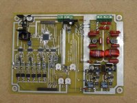
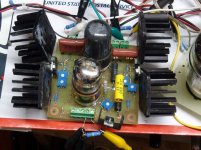
The "barebones" boards from Advanced are solder plated, so there is no copper showing. Solder shorts are a possibility, but I have done some high density QFP IC's on these boards without issue. They are not pretty though, see picture.
Attachments
Thanks for that George. Was doing some thinking on the flight today, and realised, of course, that the plate of the first stage is tied to the grid of the second, so it will be the same voltage... Also, as I will not have a negative supply on the second stage, I will have to drop around 158V, so figured using 11K here (14mA @ 158V = 11.3K). I am guessing that I can tweak the current in the loads of the second stage also to get exactly the bias I need here.
Yes i have a signal generator and a scope, so will follow your advice and tweak!
Getting very close to finalising the design here and going live! Looking forward to it!
Thanks again for the help!
Chris
Yes i have a signal generator and a scope, so will follow your advice and tweak!
Getting very close to finalising the design here and going live! Looking forward to it!
Thanks again for the help!
Chris
The "barebones" boards from Advanced are solder plated, so there is no copper showing. Solder shorts are a possibility, but I have done some high density QFP IC's on these boards without issue. They are not pretty though, see picture.
yes of course... HASL over copper - plates everything. I never run my boards that way.... almost all of our stuff is BGA's these days - and you need soldermask.
I take Sherri to the airport tomorrow. Then I will have 3 weeks to make some glow. I have found a box full of E130L's and a whole bunch of sweep tubes. I think they would look right with some 6SN7's driving them. Soon.
I have a request. I have a need for a small SPUD type amp for the office, and I know that you have one "almost" done. Care to share schematics/layout? I wouldn't mind playing around with it...
end of thread jacking - I'll start a new one on the SPUD topic ...
Schematic errors......
Hello Chris,
Thought I would write and mention that there is a few of obvious schematic errors you will want to fix. The errors I observed in the CAD schematic are as follows;
1. The lower mosfet source follower's output is connected to screen grid of the lower output tube rather than the control grid.
2. The suppressor grid of output tube(s) should be tied to the cathode on each tube.
3. The minus gas regulator tube used for the bias circuit needs to have its plate and cathode connection reversed. The plate should go to ground and the cathode to the negative supply.
I am sure you would have found these errors eventually, but I figured sooner is better than later. Have fun with the amplifier.
Doug S.")
Hello Chris,
Thought I would write and mention that there is a few of obvious schematic errors you will want to fix. The errors I observed in the CAD schematic are as follows;
1. The lower mosfet source follower's output is connected to screen grid of the lower output tube rather than the control grid.
2. The suppressor grid of output tube(s) should be tied to the cathode on each tube.
3. The minus gas regulator tube used for the bias circuit needs to have its plate and cathode connection reversed. The plate should go to ground and the cathode to the negative supply.
I am sure you would have found these errors eventually, but I figured sooner is better than later. Have fun with the amplifier.
Doug S.
Thanks for taking the time to have a look at the schematic.
The program I am using is DesignWorks Lite.
1. Connecting to suppressor from Mosfet was a mistake, have now corrected, thanks.
2. I had to make my own tube components, should have remembered to connect cathode and suppressor. A bit hard to modify now, but thanks for pointing it out.
3. Gas regulator polarity, thanks for correcting me on that, have modified.
Attached is latest, with corrections...
Thinking of lifting the voltages of the heaters for the 6SN7s. Is this required? I was thinking of 50-75volts...
Thanks,
Chris
Attachments
Thinking of lifting the voltages of the heaters for the 6SN7s. Is this required? I was thinking of 50-75volts...
Yes! The cathode voltage of the input tube is near zero. The cathode voltage of the second tube will be in the 150 volt range. In order to keep both 6SN7's within their H-K voltage ratings the filament windings should be at about 75 volts.
I laid out a simple PC board with a pair of 6SN7's using a schematic very similar to yours. I haven't had time to make one yet. Maybe this weekend.
Design suggestion
Chris,
I agree with Tubelab on his recommendation to elevate the heaters on the second 6SN7. The design thought I wanted to offer you was to simply tie your regulated +105v supply to an isolated filament winding that serves that tube, rather than to add more parts in the way of a resistive divider.
Doug S.
(aka Mickeystan)
Thanks, glad I am on track here. Unfortunately I only have one 6.3 volt winding that has to supply all tubes, so it will have to be 75volts from a resistive divider from B+.
Now, for dumb question time again...
In another thread going at the moment talking about MOSFET source followers, members are talking about the amount of current they are setting for the MOSFET using either just a resistor or CCS. In our example here (same as MOSFET Follies and tubelab driver board) we have a 10K resistor from the source to the negative supply. Is the current calculated by looking at the voltage drop across this resistor, ie difference between bias voltage (about -20v in this instance) and negative supply (-75v here) for 55v dropped across a 10K resistor to give 5.5mA?
Also, what would be a reasonable current to aim for?
Thanks again for the help!
Chris
Is the current calculated by looking at the voltage drop across this resistor, ie difference between bias voltage (about -20v in this instance) and negative supply (-75v here) for 55v dropped across a 10K resistor to give 5.5mA?
Yes.
Also, what would be a reasonable current to aim for?
It is a good place to start. I have been running my fets in the 5 to 10 mA range. Too much current and they get too hot.
Thanks Tubelab!
Makes me feel good when I think about something for a while, think I have the answer, check with the gurus and find I am right! Doesn't happen as often as I would like, but feels like it is happening more often now. You guys must be teaching me something
Seriously, thanks for the continuing help. Wish there was some way I could organise to buy you a beer to repay your efforts! Kind of difficult from Sydney though (actually in Mumbai right now!)
I have been thinking about your reference to this style of amp to Morgan Jones "Crystal Palace" amp. Maybe a suitable name will be "The Sandcastle" due to the number of voltage regulator, CCS and MOSFET chips in this thing! I don't care about that, as long as it is fun to build, sounds good and I learn something in the process
Hope you get to enjoy the upcoming experimenting!
Regards,
Chris
Hope you get to enjoy the upcoming experimenting!
It has rained all weekend, so I decided to make some circuit boards including one of these.
I got a board made this morning. Of course I found a mistake right after making it, but it isn't a show stopper. I have been populating the board today but I don't have all the right parts, so I put in what I have. Maybe it will work, maybe it will blow up, but I may get to power it up tonight.
It follows your schematic fairly closely with a few exceptions:
I didn't put in R26. (I forgot) It may or may not be needed. A capacitor to ground from the junction of R24, R25, and R26 may help avoid a low frequency oscillation. I will find out as I go along.
I did find one mistake in your schematic. You need to add resistors in series with the "bias" connections between the amp and the power supply. Otherwise the driver is looking into a very low impedance bias pot (zero ohms if the bias is adjusted to zero volts). I used 470K ohms (because that is what I had handy).
I have been thinking that since 6SN7's like voltage it might be a good idea to allow for the possibility of connecting the CCS chips that feed to plates of the second stage up to your raw unregulated B+ supply. The CCS's will block the hum and the tubes may like the headroom. Of course I didn't think about this until after I finished the board, but I am not above hacking up a PC board in the name of science. I will know more after I make some smoke.
EDIT:
I plan to try some 10M90 900 volt CCS chips in my board. I plan to explore the upper limit of 6SN7's, 6BL7's and 6BX7's. I got some of those chips about a year ago and haven't tried them yet.
I got the board powered up. I set the negative voltage to -75 and the B+ to 400 volts to match your set up. The positive supply for the mosfets is set at +25 volts since that is all that I have handy right now.
I installed the first 6SN7 and adjusted it for best results. I lowered the 330 ohm resistor in the CCS to 220 to allow more range. The pot was all the way to one end. I had to change my plate resistors to 43K in order for me to be able to adjust the plate voltage from 100 to 250 volts. Remember my resistors go directly to 400 volts. I settled on 150 volts by setting the CCS current. I could get 50 V P-P out of the first stage at low distortion.
Installing the second 6SN7 brought a strong tendency toward oscillation. It seems to be related to the mosfets or the CCS's or both. The thing wipes out the TV in the next room and it is connected to cable!
It is late here so I must shut down for the evening. I may have some time to experiment tomorrow. This weekend is a 3 day weekend in the US and it is unlikely that I would get called into work.
I plan to disconnect the mosfets and switch back to normal (10M45) CCS chips next.
Thanks George!
Yes, I wondered about the requirement for a cap at the junction of R24, R25 and R26, I just did not want to ask too many dumb questions... I have put a 20uF 450V cap on my schematic.
I placed 470k in series between bias pot and amp.
Since my amp will be point to point with some sections on perf board, bypassing the reg and putting raw B+ to second stage would not be a problem. Besides, I am only at the google sketchup build point on this amp at the moment! Since the chassis were rather expensive, I want to make sure I don't screw up the chassis layout with clashing components etc before I start cutting holes
I am away from home at the moment, working on a laptop. The schematic program I am using is designworks lite for Mac. I have been using the screenshot function on the mac to make a pdf to post the schematics, but since I have the laptop with small screen, I cannot get an acceptable resolution for a pdf that will be readable for the component values. Designworks lite has a save as pdf function, but the output is on six pages . Anyway, I will post that pdf format, please excuse the size...
Changes made are the addition of a voltage divider to lift heaters to 75V and reduced the number of secondary transformers to one, as I calculated the max current I would be asking would only be about 2/3 the current capacity of one transformer.
I have most of the components for the build now, just needing to place an order for the 10M45 chips (impossible to get in Australia!) and caps. As shipping is expensive, I want to make sure I have things worked out pretty well before ordering.
One quick question, I note you are using 0.47(?) coupling caps. I have plenty of 0.1 and 0.22uF caps and have placed 0.22uF in the schematic, will this be OK? Cannot quite work out what the impedance to ground will be through the MOSFET for the RC filter it will form. If it is just the 10K resistor to ground, then the filter freq will be 72Hz and I need to find something bigger!
Interested to read the results of the experiment!
Cheers!
Chris
Yes, I wondered about the requirement for a cap at the junction of R24, R25 and R26, I just did not want to ask too many dumb questions... I have put a 20uF 450V cap on my schematic.
I placed 470k in series between bias pot and amp.
Since my amp will be point to point with some sections on perf board, bypassing the reg and putting raw B+ to second stage would not be a problem. Besides, I am only at the google sketchup build point on this amp at the moment! Since the chassis were rather expensive, I want to make sure I don't screw up the chassis layout with clashing components etc before I start cutting holes
I am away from home at the moment, working on a laptop. The schematic program I am using is designworks lite for Mac. I have been using the screenshot function on the mac to make a pdf to post the schematics, but since I have the laptop with small screen, I cannot get an acceptable resolution for a pdf that will be readable for the component values. Designworks lite has a save as pdf function, but the output is on six pages
. Anyway, I will post that pdf format, please excuse the size...Changes made are the addition of a voltage divider to lift heaters to 75V and reduced the number of secondary transformers to one, as I calculated the max current I would be asking would only be about 2/3 the current capacity of one transformer.
I have most of the components for the build now, just needing to place an order for the 10M45 chips (impossible to get in Australia!) and caps. As shipping is expensive, I want to make sure I have things worked out pretty well before ordering.
One quick question, I note you are using 0.47(?) coupling caps. I have plenty of 0.1 and 0.22uF caps and have placed 0.22uF in the schematic, will this be OK? Cannot quite work out what the impedance to ground will be through the MOSFET for the RC filter it will form. If it is just the 10K resistor to ground, then the filter freq will be 72Hz and I need to find something bigger!
Interested to read the results of the experiment!
Cheers!
Chris
Attachments
I note you are using 0.47(?) coupling caps. I have plenty of 0.1 and 0.22uF caps and have placed 0.22uF in the schematic, will this be OK?
The cap is in the gate side of the mosfet. The gate is several megohms in parallel with a few pF. The input impedance of the stage is essentailly the resistor you just added (470K). Just about any cap will work, but too big a cap makes the bias adjustment too slow. The board that I just built has 0.1 uF 630 volt Panasonic caps in it, because they were the first ones that I found when I started building.
I was rather dissapointed with the results of last nights experiments, but it was late and I got in a hurry and tried to make it all work at once instead of going stage by stage. It may be a non issue since you are travelling, but I wouldn't get to far down the construction road until I make this thing work.
Now if I can only remember where I put those nice UTC LS57's I would have all the parts to make a nice P-P amp.
I planned to spend some time experimenting with this design over this weekend. Yesterday was the 4th of July, the American independence day, a holiday usually spent drinking beer and exploding Chinese fireworks. The city I live in puts on a professional fireworks show which I usually watch from my roof.
I spent the earlier part of the day tinkering with the board and at about 6PM there was a pounding at the door. I was met at the door by cops with their guns drawn explaining that there was a dangerous situation unfolding outside and no one was allowed out of their house until the all clear was given.
A quick look out the window revealed several officers, some carrying machine guns surrounding a house across the street. So did I hide inside my house?
No I played commando and found a good vantage point to take pictures of all this nonsense. The picture included shows an officer armed with an AR-15 assault rifle taking aim at the front door of the house. There were about 10 officers surrounding the front of the house, and plenty more in the back (not visible to me) since that is where the "bad guy" was.
This stand off went on for hours. The "bad guy" was taken into custody and hauled off to jail. The all clear order was never given, the last cop left at 11PM.
What was this all about. The "bad guy" has been out of work for several months, He got drunk and beat up his wife. She called the cops, so he took her gun and threatened to kill everyone!
So I never got around to firing up the board, or watching the fireworks.
Attachments

Sherri has been away for almost a month and she returns Tuesday, so I spent most of today cleaning up the house.
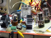
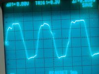
I checked outside and there were no cops so I decided to see if I could make something that sounded good. I have an octal driver board that originally looked something like chrish's design. After I cut some traces, added some parts, changed some parts, I am not sure exactly what it is now. It produces some pretty lines on a scope screen, but I can't hear them, so I wired up some output tubes. In this case they were Chinese 6L6GC's wired in triode mode. B+ was limited to 400 volts (chrish's desire) I had to raise the negative supply voltage to -105 volts, so I could crank the big tubes (later).
I warmed up these 6L6GC's on the bench to see what they would do in triode. They will make 30 watts at clip, and the distortion at 20 watts was in the 2% range.
Lines on a scope and flashing red numbers can only say so much, so it was time for the speakers and the CD player. This guy ROCKS! It plays Enya and Diana Krall very sweetly, but feed it some Mark Knopfler and it rocks.
Attachments
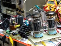
I cranked some Depeche Mode , but something was lacking. I decided that the amp needed bigger balls, so I snatched a pair of EH KT88's out of my Simple SE ans plugged them in. These would drive a 3300 ohm load and do a good job of it. I didn't make any measurements with these tubes yet, I just kept playing CD's.
Attachments
- Status
- This old topic is closed. If you want to reopen this topic, contact a moderator using the "Report Post" button.
- Home
- Amplifiers
- Tubes / Valves
- 6L6GC AB2 Amp