Hey
I have 2 pcs SE outputtrafo 12k/4 ohm. Very small (maby 20 - 30 mA) or simular.
I also have 2 pcs power trafoes with ss bridge and 100 uF cap.
B+ is 360 - 380 voltage. Bias is 35 volt dc.
6V for heat.
The power trafoes is small to.
i will try to build 2 SE mono bloks based on EL95 tubes, but i can't fine any schematics. Yes I have tried to Google.
Can some help me?
Regards
Benny
From Philips:
http://www.tsf-radio.org/forum/im/4124326922sch-phil1.jpg
Another one: AG9016:
http://www.diyaudio.com/forums/showthread.php?threadid=115649
Yves.
http://www.tsf-radio.org/forum/im/4124326922sch-phil1.jpg
Another one: AG9016:
http://www.diyaudio.com/forums/showthread.php?threadid=115649
Yves.
Benny,
I think the 1st link Yves provided points out the way. Looking at a data sheet shows power O/P will be miniscule, unless pentode mode is used.
Slew limiting is a MAJOR concern in designs that employ global NFB loops. With its very low gm, the 12AX7/ECC83 is an extremely poor candidate for the driver. Switching to the 6GK5 makes sense to me, as the type provides both high gm and high mu.
Pure pentode mode is most linear when g2 B+ is regulated. A 0A2 gas discharge type will get the job done. Another advantage of regulating g2 B+ is the modest liberty that can be taken with the anode to cathode potential difference limit. Just make sure that you scrupulously adhere to the anode dissipation limit.
Another issue in designs with global NFB is O/P trafo core saturation. Given the small O/P trafos you intend to use, attention to this detail is very important. Roll LF info. off at the amps' I/Ps at approx. 25 Hz. You bury infrasonic junk, while retaining the ability to play the lowest fundamental a double bass produces.
If extra current is available from the "6" V. filament winding, you could bring the B+ rail voltage down some by employing hybrid bridge rectifiers that use 6X4/EZ90s on the vacuum side.
The ELL80 is essentially 2 EL95 in one bottle.
We built an ELL80 spud amp and i gathered quite a bit of data.
Attached is the map of the amp we ended up building. You really need some good drive to get it to full power, so an extra gain stage at the front might be needed.
It sounds fine in pentode mode (especially with single FR speakers that like the high output impedance, but sounded better in triode (but gets down to ~1w).
dave
Attachments
You really need some good drive to get it to full power, so an extra gain stage at the front might be needed.
Dave,
Because of its very low RP, a stage gain of approx. 60X is easy enough with a RC coupled 6GK5. If that truly is not enough, front end everything else with a 12BH7 section whose cathode bias resistor is unbypassed. Do not put the extra voltage gain block inside the NFB loop. Between the natural linearity of the 12BH7 triode and local current NFB (degeneration), distortion is not a problem.
Why one channel use one more tube
Hi,
I read the schematic, why the upper channel use one more tube than the lower, would this cause 180 degree out of phase between L /R channel, need to alter the red / black spk. wire in either one channel.
planet10 said:Here is a grundig EL95 SE schema (with a common PP woofer channel)
Hi,
I read the schematic, why the upper channel use one more tube than the lower, would this cause 180 degree out of phase between L /R channel, need to alter the red / black spk. wire in either one channel.
Re: Why one channel use one more tube
Very curious indeed !
There are 3 output transformers, one per channel for trebble and one common for basses.
The EL95 are used in SE mode for stereo/trebble channels and in PP for mono/basses amplification.
The additionnal unity gain stage is a paraphase/see-saw phase splitter needed for the PP mode to work while the correct phase for stereo/trebble is restored by swapping the connection at the secondary of the transformer (black/green wires) in the -so called- right channel.
Predicting the crossover behaviour looks like a nightmare involving transformers caracteristics, caps accross them and separates feed back loops
Not so stupid for a bean counting/industrial point of view
Yves.
mitwrong said:
Hi,
I read the schematic, why the upper channel use one more tube than the lower, would this cause 180 degree out of phase between L /R channel, need to alter the red / black spk. wire in either one channel.
Very curious indeed !
There are 3 output transformers, one per channel for trebble and one common for basses.
The EL95 are used in SE mode for stereo/trebble channels and in PP for mono/basses amplification.
The additionnal unity gain stage is a paraphase/see-saw phase splitter needed for the PP mode to work while the correct phase for stereo/trebble is restored by swapping the connection at the secondary of the transformer (black/green wires) in the -so called- right channel.
Predicting the crossover behaviour looks like a nightmare involving transformers caracteristics, caps accross them and separates feed back loops
Not so stupid for a bean counting/industrial point of view
Yves.
wiring colour system
Yves:
Thanks for Ur info.,another thing make me confuse, which is is there any standard or format that define the wire colour for what purpose, for instance green colour for right channel, yellow for left,----- etc.
is there any info. about this ? Thanks
Yves:
Thanks for Ur info.,another thing make me confuse, which is is there any standard or format that define the wire colour for what purpose, for instance green colour for right channel, yellow for left,----- etc.
is there any info. about this ? Thanks
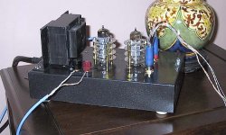
Here what I built some years ago:
A classical very simple circuit, sorry, just handdrawn.
The result looked like this:
As you can see, I replaced the ECC82 by an E80CC, this is a very very fine driver tube for this application!
Backside:
Franz
A classical very simple circuit, sorry, just handdrawn.
An externally hosted image should be here but it was not working when we last tested it.
The result looked like this:
An externally hosted image should be here but it was not working when we last tested it.
As you can see, I replaced the ECC82 by an E80CC, this is a very very fine driver tube for this application!
Backside:
An externally hosted image should be here but it was not working when we last tested it.
Franz
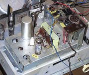
Cute? Thanks!
This how it looked inside:
I used two torroid trannies: one to step down to 24VAC, the second one to step up.
The first one had some added windings (black wire) for the heaters of the tubes.
Most of the enclosure is filled with psu parts. Two output trannies from an old SABA radio.
The smallest part of the space is used for the amplifier circuit:
Franz
/Edit
I add a picture from the brainstorming phase from this project:
This how it looked inside:
An externally hosted image should be here but it was not working when we last tested it.
I used two torroid trannies: one to step down to 24VAC, the second one to step up.
The first one had some added windings (black wire) for the heaters of the tubes.
Most of the enclosure is filled with psu parts. Two output trannies from an old SABA radio.
The smallest part of the space is used for the amplifier circuit:
An externally hosted image should be here but it was not working when we last tested it.
An externally hosted image should be here but it was not working when we last tested it.
Franz
/Edit
I add a picture from the brainstorming phase from this project:
An externally hosted image should be here but it was not working when we last tested it.
- Status
- This old topic is closed. If you want to reopen this topic, contact a moderator using the "Report Post" button.
- Home
- Amplifiers
- Tubes / Valves
- EL95 SE schematic wanted