I was lucky and scored a very, very clean Lafayette LA-234 integrated amp on fleabay. This is a 6BQ5-based amp with a few 12AX7s and 6AN8s around as helpers. I suspect it's good for 15-20W/channel. Since the phenolic sockets for the output tubes are a bit on the crispy side, I suspect that the designers aimed for the upper part of that power range. I've already popped the hood and decided to do a complete refurb, as it's almost all 10% carbon comps and dubious caps under the chassis. Even though I haven't seen a schematic just yet, I'll probably feel more comfortable ditching the current phono amp inside and starting fresh, especially judging from the schematics I've seen of earlier models like the LA-224.
Even with all the work involved, this could end up as a nifty little amp. Does anyone happen to have a schematic for this one? I've found a source for a manual, but I'm cheap.
Even with all the work involved, this could end up as a nifty little amp. Does anyone happen to have a schematic for this one? I've found a source for a manual, but I'm cheap.
Got schematic - no big surprises. 12AX7 does duty for feedback RIAA amp - will ditch this for passive EQ RIAA using 6JK8. 6LN8 triode is used as an amp for tone controls, pentode used as input for pwr amp with 1/2 12AX7 for splitter. Will look at other triode/pentode combo like 6JE8 for this duty, or perhaps other topology. Another dual triode will be used instead of 12AX7 for phase splitter. Schematic calls out 7189 outputs, 6BQ5s are actually used, with cathode bias.
This would be a comfy little amp if refurbed with circuit as-is - I would like it to be a little stunner instead.
This would be a comfy little amp if refurbed with circuit as-is - I would like it to be a little stunner instead.
The 6JK8 is a good looking tube. Thanks for the tip. However, heater draw is 400 mA., while 'X7 heater draw is 300 mA. How "beefy" is the power trafo? The tweaked RCA circuit I've been "pushing" is 100% safe. Also, the Sovtek 12AX7LPS is a true 7025 equivalent, which is important if AC is used to energize the phono section heaters.
You said the "finals" are cathode biased. That gives you the possibility of employing "Cheap Charlie" DC phono heater power, as used by H/K, et al.
A 12AU7, shared between the channels, should be decent as the phase splitters. "Concertina" phase splitter duty is (IMO) 1 of the few audio situations the 'U7 triode works reasonably well in.
Speaking of the "finals", the schematic shows 7189s, while you found 6BQ5s in situ. The Russian 6П14П-ЕВ (6p14p-ev), AKA EL84M, covers all bets.
The power transformer looks fairly sizable. I don't think Lafayette skimped too much on the iron. They did cheap out by using a voltage doubler for the B+, though. I could always load a small 6.3V transformer under the hood for extra filament juice if necessary, as there is a bit of room. This opens the possibility of running the low level filaments separately with DC. The 12AU7 is a good call for phase splitter. I may also consider the 5965, as I have quite a few of those.
I was loooking at those 6p14ps on Ebay last night. They're cheap enough to lay in a big supply for rainy days. Nice to know they're a good sub.
First off, though, I have to strip out the guts, as there are a lot of nasty old 10% carbon comps under the chassis that have had plenty of time to drift and drink up moisture. Lots of ancient electrolytics and dubious paper caps, too. Once the deck is cleared, this project shouldn't be too bad taken a piece at a time.
There is absolutely nothing wrong with a properly executed voltage doubler B+ PSU. Some of the very best amps ever made, like Marantz 8B, H/K Cit. 2, and some "Mac" models, use the topology. Back then, truly high PIV SS diodes were not available and the best of the available lot did not come cheaply. 4X diodes wired as series connected pairs and employed in the Greinacher ("full wave") topology made both technical and economic sense. What was lacking back then is sufficient capacitance in the doubler stack. Given today's greater capacitance per unit volume, that is a non-issue.
Make very sure you buy 6Н23П-ЕВ. Tubes without the suffix are 6BQ5/EL84 and not particularly good. As is so often the case, that EB suffix, which indicates highest military grade, is important in Russian stuff.
Make very sure you buy 6Н23П-ЕВ. Tubes without the suffix are 6BQ5/EL84 and not particularly good. As is so often the case, that EB suffix, which indicates highest military grade, is important in Russian stuff.
I know some Scott and Fisher amps use voltage multipliers for the main B+, as well as the others you mentioned. I understand the rationale, I'm just not in love with it... The supply is definitely undercapped. As you said, easy to fix. I may ditch the HV dropper string and gin up some regulators instead.
I took another look, and EB-suffix tubes are pretty cheap and available (for now). Time for some shopping, as if I didn't have enough tubes cluttering up the place. I have a circuit for active cathode bias. I may use it or an LED array for output stage bias. The active circuit has acquitted itself well so far in a little SE amp using a pair of 6LR8s. Check out my "Mighty Mite " thread if you're interested.
I took another look, and EB-suffix tubes are pretty cheap and available (for now). Time for some shopping, as if I didn't have enough tubes cluttering up the place. I have a circuit for active cathode bias. I may use it or an LED array for output stage bias. The active circuit has acquitted itself well so far in a little SE amp using a pair of 6LR8s. Check out my "Mighty Mite " thread if you're interested.
Sorry for the "fat finger" error in my previous post. The Russian tube that really is a 7189 equivalent is the 6П14П-ЕВ.
BTW, the 6П15П-ЕВ is a very nice tube too. However, it's screen grid is fragile. Full pentode mode with 0A2 g2 B+ regulation is fine, as is triode strapping with a 1 KOhm tie resistor. UL mode is out, unless you have separate screen grid winding O/P "iron". The data sheet for the 6П15П is here. BTW, sockets set up for the 6П15П will accept 6BQ5, etc. The other way around does not work.
BTW, the 6П15П-ЕВ is a very nice tube too. However, it's screen grid is fragile. Full pentode mode with 0A2 g2 B+ regulation is fine, as is triode strapping with a 1 KOhm tie resistor. UL mode is out, unless you have separate screen grid winding O/P "iron". The data sheet for the 6П15П is here. BTW, sockets set up for the 6П15П will accept 6BQ5, etc. The other way around does not work.
I have a dozen 6P14P-EB nailed down. They will arrive in due time. As I get stuff designed and ready to incorporate, I will post. Stay tuned for more devlopments. I may post some pictures of amp and innards before I have my ghoulish way with it. It looks nice in a utilitarian sort of way.
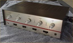
The amp - nice, clean lines, stark, uncluttered, all that rot. Sufficient motivation to put a tiger in its tank.
Are you going to deal with the concentric, non-ganged, controls? I see 5 openings in the faceplate, which could hold: a source selector, separate L/R PEC volume controls, and tone controls, which are ganged.
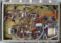
The innards - the usual hand-wired hodgepodge. Things will change.
Whatcha got planned? Do I see salvagable WW resistors in there?
Right now, what I want to concentrate on are developing some new functional blocks - the RIAA amp and power amp for starters. Next up is to decide how it's all strung together, whether or not to ditch or keep the tone controls or replace (or supplement) that block with a lineamp/preamp out. It's going to be a bit of a challenge - all stages (except for perhaps the finals) are pretty current starved, and I'm planning on replacing the 12AX7s with tubes that will demand more plate and filament current in order to shine. I have a fairly large assortment of used/NOS power iron. If necessary, maybe I can find a beefier power transformer that will drop in.
The usable wirewounds are probably only usable (in this project, at least) if I preserve the traditional dropper string.
So, first up is breadboarding some blocks with my new PVC breadboarding sockets. Even if I don't use the new circuits in this project, they'll be useful elsewhere.
A useful interim step may be to shotgun the electrolytics, carefully bring the amp up, and measure voltages in the circuit as-is, as well as output stage quiescent current. The schematic ain't exactly
Howard Sams.
Anyway, this will be sandwiched in with other projects in progress that are definitely lower hanging fruit.
12AX7s in the phono section are OK. I've got a tweaked RCA circuit that WILL get the job done. Yes, it has decent drive capability and working into 50 KOhm volume controls is "a piece of cake". Building a regulated 300 mA./12 VDC supply for the 'X7 heaters is very easy. That gives you more heater current out of the OEM power trafo for your line/driver tube type changes.
If you forego tone controls, A 12AT7 section as the voltage amplifier DC coupled to a 12BH7 section as a "concertina" phase splitter (Fisher/Dyna style) will work out nicely. The 'T7 sounds very good in PP amps and its low RP allows it to compete well against, the 'X7 in the net gain dept. A 200 - 220 V. 'T7 anode to cathode potential difference and an IB of 3 mA. is nice.
If you forego tone controls, A 12AT7 section as the voltage amplifier DC coupled to a 12BH7 section as a "concertina" phase splitter (Fisher/Dyna style) will work out nicely. The 'T7 sounds very good in PP amps and its low RP allows it to compete well against, the 'X7 in the net gain dept. A 200 - 220 V. 'T7 anode to cathode potential difference and an IB of 3 mA. is nice.
Eli, I have some different ideas I want to try - I'm a stubborn old cuss who wants to find his own way and try his own notions. One of my notions is to avoid any use of 12AX7s. As you said, the 6JK8 is a nice-looking tube, and I want to hear if it's worth the trouble. I'm not in any big hurry, and I'll probably try a few things outside before settling on the solutions I want to tuck into the chassis. I see a bit of sand (maybe some GaAlAs or GaAsP, too) in this amp's future...
One thing is for certain, I'll be making pretty much a clean sweep inside, down to replacing the majority of the sockets. The output tubes have crisped their phenolic sockets, so those positions will get some fresh ceramic numbers.
One thing is for certain, I'll be making pretty much a clean sweep inside, down to replacing the majority of the sockets. The output tubes have crisped their phenolic sockets, so those positions will get some fresh ceramic numbers.
The output tubes have crisped their phenolic sockets, so those positions will get some fresh ceramic numbers.
Jim McShane has pointed out that ceramic sockets can conduct vibration into the tubes. Jim suggests that mica loaded phenolic sockets be used. They resist charring and they also damp vibration.
")
One of my notions is to avoid any use of 12AX7s. As you said, the 6JK8 is a nice-looking tube, and I want to hear if it's worth the trouble.
The 6JK8 draws 400 mA. of heater current. The same sort of regulated 12 VDC heater supply, as used with 'X7s, is OK. Just wire the 2X heaters in series.
The small footprint and low stray mag. field of a toroidal power trafo work to your advantage. Use a MBR20100CT to FWCT rectify the O/P of an AnTek model AN-0212. Filter with a high value 'lytic. Finish up with a 7812 3 terminal regulator.
First Installment -
ditch the HV dropper string and run the preamp stages and output screens using this HV series regulator. I brought up a prototype this afternoon using a HV PNP instead of the P-Channel MOSFET pass element, and it regulated just fine. I just sent off to Mouser for the MOSFETs, so I should be testing the real deal next week. 250V is probably less than the output tube screens want to see for max power, but the innards are less complicated if I don't use yet another regulator for the screen supply. B+ is about 350V.
ditch the HV dropper string and run the preamp stages and output screens using this HV series regulator. I brought up a prototype this afternoon using a HV PNP instead of the P-Channel MOSFET pass element, and it regulated just fine. I just sent off to Mouser for the MOSFETs, so I should be testing the real deal next week. 250V is probably less than the output tube screens want to see for max power, but the innards are less complicated if I don't use yet another regulator for the screen supply. B+ is about 350V.
Attachments
wrenchone said:This would be a comfy little amp if refurbed with circuit as-is - I would like it to be a little stunner instead.
You should consider the phase splitter out of Eli's El Cheapo... the build we have with a Scott donor is outstanding...
dave
Preliminary schematic for the RIAA block... I expect it will change a bit during breadboarding, with some tweaking on the input resistors for the RIAA filter, and some messing around with the values around the output stage. I'm handicapped by not having any curves for this tube, so I'll have to throw the thing on the bench and play a bit. I would like to tone down the gain on the output stage a bit, yet still have decent voltage centering. I have some Rohm IR LEDs that I'll be trying for input stage bias. The JFET current source provides extra bias current for the LED to help nail the bias point.
Attachments
- Status
- This old topic is closed. If you want to reopen this topic, contact a moderator using the "Report Post" button.
- Home
- Amplifiers
- Tubes / Valves
- Lafayette LA-234 Amplifier