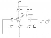
I am having a glow tube issue, and I am totally stumped what is going on. I have a stereo line stage as attached. When I turn it on, one side's glow tube will glow, and the other won't. When I move the tubes from side to side, sometimes the side that strikes changes, and sometimes it doesn't. In fact, while certain tubes strike more often than others, it is somewhat random which side will light up. Moreover, I have a pile of these tubes, all are good, and some of them seem faster than others.
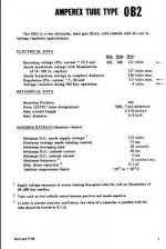
The 6T4 runs with about 70V on the plate when biased with a red LED. The 0B2 is supposed to strike at 133V (or maybe 115 -- different sources say different things). At any rate, if the mosfets are left out, both sides strike with no issue (essentially with just a 30mA CCS running through them). So, it is definitely the addition of the mosfets that is causing the issue.
I tried increasing R8 to 22K in case there was current being drawn, but it does not seem to be the case as the 6T4 is still running at the right spot. Also, the mosfet's source resistors are dropping the right amount of voltage. So, there must be current running through the 0B2's (~20mA each) but only one lights up or gets warm. Though, even the non-glowing one seems to be regulating.
I think I am at the limit of my abilities here to diagnose this. Can anyone offer any suggestions?
Attachments
I think what might be happening is that the voltage is initially high and the first one strikes. This causes the voltage to sag. At this point, the other mosfet is biased to B+ since the 6T4 is not yet conducting. As such, it draws too much current which keeps the second 0B2 from striking.
If this is right, then either increasing the source resistor or cap coupling and biasing with a voltage divider, might work. The former will reduce the current it can supply, the second adds another cap, so I'm not really in favor of either. Maybe a higher B+ is an option. But, I am going to try these other options first to see if one works.
If this is right, then either increasing the source resistor or cap coupling and biasing with a voltage divider, might work. The former will reduce the current it can supply, the second adds another cap, so I'm not really in favor of either. Maybe a higher B+ is an option. But, I am going to try these other options first to see if one works.
Was that the first cap you tried? I've tried both 0.1u and 0.022u, and neither seems to help. Increasing the source resistor to 15K didn't help.
I think a higher B+ would help, and the power transformer I have hums something awful, but I am feeling too impatient to wait for a new transformer to to ship.
I think a higher B+ would help, and the power transformer I have hums something awful, but I am feeling too impatient to wait for a new transformer to to ship.
Another clue? The mosfet on the side with the lighted tube has ~5mA through it, which means the glow tube has 25mA. On the non-lighted side, the mosfet has 3mA with 27mA for the non-lighted tube. B+ measures at 163V. The lighted tube gets warm, the other doesn't. It is like the CCS isn't actually putting out current, or it is going somewhere else. Which doesn't make sense as the one glowing switches sides.
Starting voltage for VR tubes is always higher, but you need to be careful not to run them too hot. I have a pair (0A2 and 0B2 in series) in an old preamp design used for shunt regulation. They are driven by a 15ma current source. The power supply has solid-state rectification, so you get an initial higher voltage which is sufficient to light the VR tubes (CCS pass device is a single Mosfet). Point being the (circuit) load on the supply comes after the VR tubes are lit, hence they have full current available (for lighting) before the load appears.
As you have two individual channels, when the first one lights, you immediately draw 30ma of current from the supply. It's voltage probably drops enough so the second VR tube doesn't have sufficient voltage to start. Monitoring the B+ with a scope on slow-sweep would confirm this (or not). Is the power supply using tube rectification? This would cause a delay in B+ voltage, meaning both of the 6T4 triodes are probably conducting current (40ma) before the VR tubes have a chance to light due to the voltage drop from the supply.
If this is the case, you could drop the CCS value from 30ma per side to ~15ma. This would put less load on the supply and perhaps allow both tubes to light.
Regards, KM
dsavitsk said:Hmmmm. I used a 144VAC transformer rather than the 120 I was using which increased B+ to 170V or so. I also tried cap coupling the mosfets and biasing them to 1/2 B+, and using 15K source resistors to cut down on the current. Still, one glow tube lights, the other doesn't.
Starting voltage depends on ambient light: photons cause initial ionization of gas. In darkness they need higher voltage to start.
There was an electronic instrument called Ionika where neon bulbs used for each key to modulate sounds. One wire with applied high frequency was going near bulbs, but bulbs were shielded from it by shields on keys. When a key was pressed corresponding shield opened RF radiation to the bulb so it started glowing and conducting.
It is solid state rectified, so the glow tubes come on instantly, or at least one of them does.
Also, if I remove the mosfets completely, both glow tubes light just fine with the same current draw. And, B+ is well over 160V even with full draw.
Even weirder, with one glow tube removed, both mosfets have 109V on the drain. With both tubes removed, this is not the case. This would seem to suggest a wiring error, except that they are on different sides of the chassis, and don't share any connections other than to ground. But, I think I need to remove all of the wiring and start from scratch as I feel like i must be overlooking something dumb.
Wavebourn said:
Starting voltage depends on ambient light: photons cause initial ionization of gas. In darkness they need higher voltage to start.
There was an electronic instrument called Ionika where neon bulbs used for each key to modulate sounds. One wire with applied high frequency was going near bulbs, but bulbs were shielded from it by shields on keys. When a key was pressed corresponding shield opened RF radiation to the bulb so it started glowing and conducting.
Most of the later manufactured VR tubes had some radioactive material (isotopes) added to help in the area. The tubes actually have the old radioactive symbol (3 triangles arranged in a circle) printed on them and disposal was suppose to be controlled. My preamp which employs these uses NOS JAN spec VR tubes which have the radioactive isotopes and associated markings. I built around 8 of these preamps during the late 80's and as far as I know, all are still in operation today. They operate in complete darkness and only on one occasion did I have an issue with one of the VR tubes having a tendency to oscillate, replacing it solved the issue.
Regards, KM
dsavitsk said:It is solid state rectified, so the glow tubes come on instantly, or at least one of them does.
Also, if I remove the mosfets completely, both glow tubes light just fine with the same current draw. And, B+ is well over 160V even with full draw.
Even weirder, with one glow tube removed, both mosfets have 109V on the drain. With both tubes removed, this is not the case. This would seem to suggest a wiring error, except that they are on different sides of the chassis, and don't share any connections other than to ground. But, I think I need to remove all of the wiring and start from scratch as I feel like i must be overlooking something dumb.
It would appear that you may have the VR tubes strapped in parallel. I would check for this before gutting and starting over. I would also suggest that you could probably run with a single common VR tube as it only provides a reference voltage for the Mosfet and is not an active component in the signal chain. Depending on how your current source operates, there may be a minimum voltage drop it requires before current regulation takes place.
Regards, KM
Tom Bavis said:Are the FETs on a heatsink? Insulated from the heatsink?
Bingo! They both use the chassis as a sink, and have insulator pads, nylon screws, shoulder washers, etc, so I assumed they were well insulated. I guess not. Its a wonder I didn't zap myself ... or blow the PS fuse -- I'll have to figure out why that didn't happen.
- Status
- This old topic is closed. If you want to reopen this topic, contact a moderator using the "Report Post" button.
- Home
- Amplifiers
- Tubes / Valves
- Glow Tube (0B2) Help