Hello gentlemen,
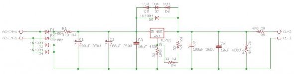
Below is my attempt at a regulated 250v PSU, for driving two E88CC triodes.
Any comments/suggestions?
All capacitors except 10uF are Aluminum Electrolytic, 10uF are MKP.
Resistors are metal film 5%, 2W.
I tried searching the forum for similar designs but nothing concrete came up.
Thanks
Below is my attempt at a regulated 250v PSU, for driving two E88CC triodes.
Any comments/suggestions?
All capacitors except 10uF are Aluminum Electrolytic, 10uF are MKP.
Resistors are metal film 5%, 2W.
I tried searching the forum for similar designs but nothing concrete came up.
Thanks
Attachments
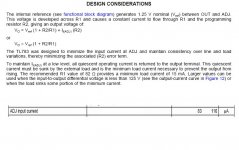
To "regulate" the TL783 needs to see at least 15mA load -- so you need current of this amount to flow from the output to adjust -- Texas Instruments recommends 82R.
Make sure that you use an adequately sized resistor from the adjust pin to ground -- at least 5 watts, preferably 7 watts.
So Output to Adjust 82R, Adjust to Ground 16K/7W.
The series resistor in the output -- omit this.
Read the data sheet from TI.
Make sure that you use an adequately sized resistor from the adjust pin to ground -- at least 5 watts, preferably 7 watts.
So Output to Adjust 82R, Adjust to Ground 16K/7W.
The series resistor in the output -- omit this.
Read the data sheet from TI.
Yes but, no but, yes but, no but....
15ma across 82 ohms is 0.018 W.
15ma @250V is 3.75 W.
So, you're just burning energy -- if you're running a Class-A amp and the device is going to cook anyway -- it doesn't matter. If the load is going to vary all over the lot, then the lower value from OUT to ADJ is a better idea.
Anyone who runs a class-A amplifier will probably be hunted down by the next Stateside Administration. I hear that the Green Wing of the Dem party wants them outlawed -- and we'll all be listening to MP3's on Class-D amplifiers anyway.
jackinnj said:Yes but, no but, yes but, no but....
15ma across 82 ohms is 0.018 W.
15ma @250V is 3.75 W.
So, you're just burning energy -- if you're running a Class-A amp and the device is going to cook anyway -- it doesn't matter. If the load is going to vary all over the lot, then the lower value from OUT to ADJ is a better idea.
Anyone who runs a class-A amplifier will probably be hunted down by the next Stateside Administration. I hear that the Green Wing of the Dem party wants them outlawed -- and we'll all be listening to MP3's on Class-D amplifiers anyway.
Jackinnj,
ROTFLMAO!
Well said. I'm putting nighttime covers on my tubes...
Ron
jackinnj said:-- and we'll all be listening to MP3's on Class-D amplifiers anyway.
This is a base slur. Class-D amplifiers yes, but nobody said anything about MP3s, which everybody knows are intrinsically more power hungry than uncompressed.
I know it's your politics, but the whole world's praying we don't get another idiot like the last one. Even us atheists.
w
I'm a republican too, it just means something different when you live in a monarchy.
wakibaki said:
I know it's your politics, but the whole world's praying we don't get another idiot like the last one.
I'm a republican too, it just means something different when you live in a monarchy.
Your entitled to your opinion....but not here. This is an inappropriate thread / forum for that type of comment. Let's stick to Audio related comments. OK?
Hey, I have my thoughts too, but this 'aint the place.
Personally, I don't like being told what I can or cannot do by my government. No one was called any names or attacked in the posting of this message.
Ron
(and I approve this message)
wakibaki said:
This is a base slur. Class-D amplifiers yes,
As long as you shield the Class-D amplifier in a Faraday Cage...
Getting back to the matter at hand, the TL783 would probably benefit from a MKP from adjust to ground -- this will knock down the noise quite a bit (although it isn't helpful for transient response, as TI points out.)
Just remember, JOBs is a 3-letter word, spread it around.
Originally posted by various people here
I would lose the large 100uF cap on the output
-----
we don't get another idiot like the last one.
I have my thoughts too, but this 'aint the place.
I could have done better, and I have no political skills whatsoever...
Back to audio: I'd be worried if that regulator could take it if the output should get shorted to ground, or takes enough of a nosedive to overvoltage the regulator's ratings. The cap will look like a short for some brief period of time, long enough to kill the regulator. Instant chip death, and probably will blow shorted, feeding unregulated full B+ to the load. Doesn't take much to kill semiconductors, transients tubes laugh at will take out solid state.
jackinnj said:Yes but, no but, yes but, no but....
15ma across 82 ohms is 0.018 W.
15ma @250V is 3.75 W.
So, you're just burning energy -- if you're running a Class-A amp and the device is going to cook anyway -- it doesn't matter. If the load is going to vary all over the lot, then the lower value from OUT to ADJ is a better idea.
Sorry but I don't agree.
The datasheet clearly states that ADJ current is negligible, so the current returns to GND via the 82 Ohm and the other setting resistor, that has to dissipate a lot of power. Try to put a trimpot there!
So who's burning energy?

I just said that if the minimum load current is 15mA or more there is no need to add a further load to the supply.
Ciao!
Andrea
Attachments
OK, the ADJ input current is MAX 110 microamps. To keep the divider 'stiff' you want about 10 times this current or 1 mA down thru the divider. At 250 V this is obviously a net resistance of 250k. The power dissipated in this limb is a quarter watt. You woudn't need the 2W rating shown for the upper resistors, if you go this route. 1W will be conservative in the lower and a quarter watt in the upper (~1250R).
The 10k (25mA) at the output will ensure the device stays in regulation obviating the other reason to pull more current thru the divider, but it is dissipating over 6 Watts, and the 2W part in the diagram is totally inadequate. If you know your application will always draw more than 15 mA this part is redundant.
If you need the quiescent current you can choose to pull more current (>15mA) thru the divider and again dispense with the 10K, You of course get a stiffer divider but you will need to uprate the lower resistor to cope. I would go this route with the recommended 82R in the upper resistor and a calculated 16318R in the lower, which will be dissipating ~3.8W at just over 15 mA. Follow the manufacturers recommendation for the physical placement of these resistors.
I wouldn't put a cap from ADJ to ground, the datasheet specifically recommends against. You can always leave room for it to try later if you feel the performance is lacking, but right now it's just another thing to go wrong.
'can... create a need for extra protection circuitry' does not sound trivial to me.
The datasheet shows a 10u cap at the output, which is 20 times the min. recommended at this voltage I don't see the necessity for the 100u or the 470R series resistor.
The datasheet also shows an arrargement with short-circuit protection, so I presume you have considered this...
w
Matt the E said:Thou hypocrite, first cast out the beam out of thine own eye; and then shalt thou see clearly to cast out the mote out of thy brother's eye ...
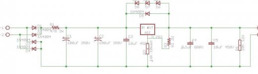
Assuming I want this PSU to be compatible with any further project requiring these voltages, I rather not assume a constant load of 15mA. In that case I believe it is indeed right to go with the 82/16k values:
However, there might be slight problem with the 82 and 16k resistors - these are not values which are easy to find at these wattage/voltage ratings.
The 82 does not need a high wattage rating so it can be built from 2 resistors. The 16k however does need a high wattage rating.
At the moment, all my resistors are of metal film type. Should I look for something else? Does the tolerance matters?
I am hoping to be able to source it from digikey - at the moment all the parts I need are available there.
On the same subject, does the quality of the resistors in this PSU or similar (utilizing LT1085 for example - used for heaters 6.3 regulated rail) really matters?
What should I look for?
Many thanks.
Also, regarding the protection circuit suggested at the datasheet. I do have the 120v zener, but without the transistor. With my limited knowledge of electronics, I fail to understand its purpose on providing a protection against a short circuit. I would appreciate an explanation.
eranrund said:
Also, regarding the protection circuit suggested at the datasheet. I do have the 120v zener, but without the transistor. With my limited knowledge of electronics, I fail to understand its purpose on providing a protection against a short circuit.
The zener diode is to keep the regulator from ever seeing more than 120V from its input to its output. A short on the output should drag down the unregulated B+ source down to 120V above ground. I looked at this chip's datasheet, and it can take up to 120V.
The resistors need not be anything fancy, but for better reliability, I'd use resistors at least twice the power rating you expect them to ever have to handle.
Twice... that would be around 10-14Watt. Only types I know that reach these ratings are wirewound and I will probably have to combine a few to reach the desired values, and have them mounted on the case and not the pcb (am I right here? or will the PCB survive this assuming they get mounted on a heatsink)
- Status
- This old topic is closed. If you want to reopen this topic, contact a moderator using the "Report Post" button.
- Home
- Amplifiers
- Tubes / Valves
- TL783 regulated B+ 250V PSU schematic