Vacuum rectifiers
I will admit that vacuum rectifiers may sound different. I see them as introducing intermodulation distortion due to poor regulation. If you like the distortion, it is a good thing.
The information, on the high speed diodes just confirms my theory. The switching artifacts are above 120 hz and thus removed by the filter components.
As far as seeing it on a scope the ripple, on my 400 volt supply, is less than 1 volt. The regulation holds within 2 percent.
Valveluver
SS rectifiers exhibit wide band switching noise which on it's own is very likely inaudible but mixed with you favourite music in different stages of an amp will contribute to 'electronic glare'. Your best bet is to compare sonics of SS and vacuum rectifiers and decide for yourself. If it sounds the same consider yourself lucky - one less worry in your audio designs and less chances of developing fully-blown audio paranoia") Make this decision based on your own ears, not Frank's or Joel's.
Make this decision based on your own ears, not Frank's or Joel's.
This type of noise is certainly measurable but not easily visible on a scope - we're talking narrow spikes with lots of hi-freq content but low repetition rate. And of course this has no resemblance to innocent 50/60Hz hum which even the less gifted seem to be able to hear
cheers
peter
SS rectifiers exhibit wide band switching noise which on it's own is very likely inaudible but mixed with you favourite music in different stages of an amp will contribute to 'electronic glare'. Your best bet is to compare sonics of SS and vacuum rectifiers and decide for yourself. If it sounds the same consider yourself lucky - one less worry in your audio designs and less chances of developing fully-blown audio paranoia
Make this decision based on your own ears, not Frank's or Joel's.This type of noise is certainly measurable but not easily visible on a scope - we're talking narrow spikes with lots of hi-freq content but low repetition rate. And of course this has no resemblance to innocent 50/60Hz hum which even the less gifted seem to be able to hear
cheers
peter
There is a lot of stuff in the link Frank that references articles on the problems caused by the reverse switch off spike that diodes exhibit and the hf noise that this causes in the psu....
What does this sound like and how does it affect the audio?
Typically this is wideband noise that might extend down into the middle of the audio band but most of the energy is at 100KHz up into the multiple MHz region. These high frequencies are typically not attenuated by the psu components, for instance psu chokes parasitic capacitance shorts the choke out at these frequencies. They are then injected into the audio circuits where they modulate / mix with each other and the audio signal. They are normally relatively low level so this acts to 'grunge up' (technical term ) the sound in valve amps without feedback and in valve or ss amps with trans-stage feedback they really coursen the sound and extend the higher order distortion components leading to rapid listening fatigue...
hope this helps
ciao
James
What does this sound like and how does it affect the audio?
Typically this is wideband noise that might extend down into the middle of the audio band but most of the energy is at 100KHz up into the multiple MHz region. These high frequencies are typically not attenuated by the psu components, for instance psu chokes parasitic capacitance shorts the choke out at these frequencies. They are then injected into the audio circuits where they modulate / mix with each other and the audio signal. They are normally relatively low level so this acts to 'grunge up' (technical term
) the sound in valve amps without feedback and in valve or ss amps with trans-stage feedback they really coursen the sound and extend the higher order distortion components leading to rapid listening fatigue...hope this helps
ciao
James
The filter components (chokes and caps) generally don't do much to very sharp noise spikes. Nor do regulators unless they still work in high MHz region. If what you non-believers say is true a vac rectifier can easily be emulated by SS and a series resistor but practice shows this to sound terrible.
Valve rectifiers are clearly audible even after extensive regulation. Once i built a phono-pre with a transformer supplying way too high voltage. It burnt the excess in multiple RC/LC filters and used a ridiculously large main filter cap - 3300uF. This cap was being charged through nearly 100kohm resistor and still the character of the rectifier was clearly audible.
cheers
analog_sa said:And of course this has no resemblance to innocent 50/60Hz hum which even the less gifted seem to be able to hear
But 100/120Hz is not innocent. I saw him did it!
Goertz Bridge?
Hi Thomas,
I assume you are talking about the Goertz Bridge? A Hybrid bridge rectifier configuration. There is quite a bit on the web about it a google search with find a few references.
I am building one at present with BYV26Es and an 83 to power my 6B4G pp amp. I ahve a cheap source of good quality psu transformers but the ht windings do not have a centre tap so I'm using ss BR at present and want to see if I can hear the difference with an 83 in the circuit... more later I'm sure.
I have just tried it with a BYV26E bridge and that sounds very good - much better than 1N4007 with snubbers and, surprisingly, better than the 5U4 psu that feeds my sons 2A3 PSE amp.
So I say try it - you may well like it...
 One observation - that is often made and just as often overlooked! All these implementations are system dependent.
I'm sure with different transformers etc. the 5U4 can sound better than the BYV26Es... And I know in some circuits that the 1N4007 with snubbers can sound as good as a GZ34 - not evry circuit but certainly in some...
ciao
Jmaes
Hi Thomas,
I assume you are talking about the Goertz Bridge? A Hybrid bridge rectifier configuration. There is quite a bit on the web about it a google search with find a few references.
I am building one at present with BYV26Es and an 83 to power my 6B4G pp amp. I ahve a cheap source of good quality psu transformers but the ht windings do not have a centre tap so I'm using ss BR at present and want to see if I can hear the difference with an 83 in the circuit... more later I'm sure.
I have just tried it with a BYV26E bridge and that sounds very good - much better than 1N4007 with snubbers and, surprisingly, better than the 5U4 psu that feeds my sons 2A3 PSE amp.
So I say try it - you may well like it...
One observation - that is often made and just as often overlooked! All these implementations are system dependent. I'm sure with different transformers etc. the 5U4 can sound better than the BYV26Es... And I know in some circuits that the 1N4007 with snubbers can sound as good as a GZ34 - not evry circuit but certainly in some...
ciao
Jmaes
GOERTZ BRIDGE??
Hi,
If it is what I think it is than the diodes ( the silicon ones) would still benefit from snubbers.
To me, the main beauty is that it provides a slowstart as well.
Hi James,
Are you sure this is what it is called? It's not a Graetz bridge, but a Goertz bridge?
Cheers,
Hi,
Do U had experience that use non- CT winding transformer that mix with diode(IN4007) & tube(5U4) to rectifiy in 300B amp.
If it is what I think it is than the diodes ( the silicon ones) would still benefit from snubbers.
To me, the main beauty is that it provides a slowstart as well.
Hi James,
Are you sure this is what it is called? It's not a Graetz bridge, but a Goertz bridge?
Cheers,
RF noise from solid state rectifiers
If the noise occurs at or about 100Khz, the filter choke will take it down more so than the power supply ripple. The inductive reactance, of a 10 henry choke @ 100Khz is +j. 6,200,000. If a 100 Khz component appears on a DC supply, it is poorly designed.
If the noise occurs at or about 100Khz, the filter choke will take it down more so than the power supply ripple. The inductive reactance, of a 10 henry choke @ 100Khz is +j. 6,200,000. If a 100 Khz component appears on a DC supply, it is poorly designed.
IT AIN'T THAT SIMPLE.
Hi,
And no, that won't be all that effective...
Once again read the info given by Fred Dieckman, digest it and just like me, you'll realise that audio is a big jungle,
A scope is a really handy tool, not a luxury.
Ciao,
Hi,
If the component is in the Mhz range a mica bypass capacitor would take it out. A .01MFD capacitor is a -j. 13
And no, that won't be all that effective...
Once again read the info given by Fred Dieckman, digest it and just like me, you'll realise that audio is a big jungle,
A scope is a really handy tool, not a luxury.
Ciao,
...poor spullen...
Hi Frank,
Frank said
You are 100% right! Sorry. I'm dyslexic - so this sort of mis-spelling is very common with me
You should see my attempts at learn a new language
I agree with the diodes still benefiting from snubbers in a Graetz bridge - that has been my experience with 1N4007.
Valveluver
Actually a 100Mhz scope won't capture most of this RF noise by just hooking it accross the psu rails... The noise is burst in nature and (relative to the B+) low level. It can be done using a 'B delayed' set up but it is still very difficult to sync the B delayed with the reverse recovery spike.
But then if you have 'a complete audio test facility' you have a 1GHz bandwidth spectrum analyser with 80dB range and this will show this noise very very clearly - you can then see how ineffective your suggestions at filtering these components out will be.... ( I wish they did work!!!)
ciao
James
Hi Frank,
Frank said
Are you sure this is what it is called? It's not a Graetz bridge, but a Goertz bridge?
You are 100% right! Sorry. I'm dyslexic - so this sort of mis-spelling is very common with me
You should see my attempts at learn a new language
I agree with the diodes still benefiting from snubbers in a Graetz bridge - that has been my experience with 1N4007.
Valveluver
Actually a 100Mhz scope won't capture most of this RF noise by just hooking it accross the psu rails... The noise is burst in nature and (relative to the B+) low level. It can be done using a 'B delayed' set up but it is still very difficult to sync the B delayed with the reverse recovery spike.
But then if you have 'a complete audio test facility' you have a 1GHz bandwidth spectrum analyser with 80dB range and this will show this noise very very clearly - you can then see how ineffective your suggestions at filtering these components out will be.... ( I wish they did work!!!)
ciao
James
BETTER THAN NOTHING...
Hi,
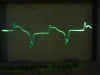
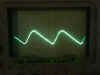
To give you some idea of the (lack of) effectiveness of a snubber here's a screenshot of a scope.
This is the nasty **** going on next to the snubber capacitor. The vertical voltage scale is 50 mV/div. Notice the sharp spikes of HF, almost 150 mVpk.
The diodes are your everyday IN4007s, byspassed with a 1nF cap and a 150R in series.
Cheers,
Hi,
To give you some idea of the (lack of) effectiveness of a snubber here's a screenshot of a scope.
This is the nasty **** going on next to the snubber capacitor. The vertical voltage scale is 50 mV/div. Notice the sharp spikes of HF, almost 150 mVpk.
The diodes are your everyday IN4007s, byspassed with a 1nF cap and a 150R in series.
Cheers,
Attachments
- Status
- This old topic is closed. If you want to reopen this topic, contact a moderator using the "Report Post" button.
- Home
- Amplifiers
- Tubes / Valves
- Tube Regulator