Hello ,
As I am about to build a PP amplifier for a pair of 6550a, and I would like to ask, if someone has experience to the drive circuit - input and driver.
The intension was to use the old circuit from Michaelson & Austin, but if some DIY people has experienced and tested a better configuration for the Tungsol 6550a tubes , I really would appreciate some help with the circuit stucture.
Has anyone out there some knowledge for a modern, or more up to date design, when we speak about the 6550a tubes?
I like symmetrical designs - Is D76/D79 from Audio Research a possible option? - and does it sound better than the mentioned circuit from M&A?
The plan is a fet regulated high volt psu for the input - and drive tubes.
Rgds
I'm of the opinion that 6550s, like 6L6s, KT88s, EL34s etc, are very easy tubes to drive. They require no special drivers per-se. They can all be capacitor coupled right from the plates of the previous stage assuming that has the required gain and balance. Of course a cathode follower driver is good design, but not truly necessary. For push-pull, fixed bias is the way to go with not much more then 50K ohms in the grid to ground circuit. Although I have seen more used.
AR used a cross-coupled interstage tube to help balance the phases through it's positive feedback. Probably because they used a screw-ball unity gain stage to invert phase right at the input. It worked but was more complicated then need be. A well designed long-tailed pair with a CCS in the tail is a much better way to phase invert a signal.
There are many dozens (perhaps hundreds) of circuits for PP 6550s (or others) out there for the taking. Most will sound good if properly implemented. My advice is, first, use the very best output transformer that you get or afford. This is the heart of a tube amplifier and is the most important part for good performance. Second, chose a circuit that uses only one capacitor in the signal path. (each phase) Any more then one is unnecessary.
Regulate the input and driver if you want. But since they almost always run in class A, regulation won't buy you much and I doubt if you'll hear a big difference provided they are properly decoupled from one another. Meaning an R and C between feed points.
Victor
Hello Victor!
Thanks, - I was not sure whether the cross-coupled interstage tube , and the cathode follower design as in D79 was necessary in order to get the phase right, and secondly - was it really necessary to use that many tube stages to drive a pair of 6550's? A larger number of tubes was seen in McIntosh 275 as well ( one amp I have never heard) . I have listened to the D79 and the sound , after my opinion, was soft and still with good attack in the deep region.
I understand , and what I hoped for, that the long tailed pair and a high performance output transformer are the more important issues when building a good tubeamp.
Could you please let me know what "CCS" is? Please let me have your opinion at the attached TVA-1 design. THe circuit contain not two, but four caps ( two phace) , and you advised me of having only one pair. Third ( I promise to stop now) Could you recommend any output transformer of high quality - We got "Sowter", and "Lundahl" in Europe?
Best rgds
Kim
Attachments
There are so many issues; what B+ ; o/p power?; input sensitivity
are you after ?
A concertina phase splitter with Williamson interstage driver will give a lower output Z to the output tube grids hence better top end performance than the longtail phasesplitter , esp when quite low value grid leaks are used for the output stage. This is a tough challenge esp for distortion.The Svet 6550C version quotes around 100K for fixed bias, which is a darned sight better than 50K for the early A version but I’m not sure about the value with TungSol reissue tubes.
Read up Morgan Jones, 4th edit Valve amp p. 415 mentions the poor performance of the Mullard 5-20 which uses an ECC83 as LTP and one should avoid this signal tube for such tough tasks.
. If you are looking at a -3dB response at 50Khz with a good quality output transformer then expect a driver stage to consume current to deliver the goods and to avoid early response slewing and distortion.
There are other issues, a 3 stage design is more stable than a 4 but with correct optimisation a 4 can be made just as good.
The 3 stage configuration shown in the Radford STA25 Renaissance which uses an ECC88 cascade and 6U8A (ECF80/2) as a beefier longtail pair into 6550’s, could be the configuration you want. At the moment I cannot copy pics.
If you aim for good interstage driver performance then I find 6550’s give better sonic performance than KT88’s (O.M.V).
As Victor mentions, a top notch output tranny is instrumental to performance.
I regulary use an ECF80 as concertina p/s followed by Williamson config 12BY7’s as triodes (expect 30mA current per pair); driving 6550’s and I get very low thd.
A four stage amp using a concertina p/s with 20dB global nfb with give a signal/noise ratio around -60-70dB down whereas a 3 stage using a LTP using the same global nfb should acheive nearly - 85-90dB down.
The -60dB noise figure will just be noticeable from a tweeter in the average distance/ listening position esp when a pentode is used as the input gain stage. I often use a pentode duped as a triode, this is useful when a line sens approx 0dBv (0.77V) is only used, signifigantly reducing the circuit noise.
The beauty of the concertina arrangement is no circuit tweaking for balance, whereas a LTP requires a pot /present to balance out for min thd.
If you use the concertina p/s, make sure the B+ psu ripple rejection is high, as the anode has a far lower PSRR.
richj
Re: Hello Victor!
Hi Kim,
CCS means "constant current source". It is a means of controlling current flow through the tubes and keeping it at a constant level as well as providing signal isolation. It can be as simple as a single LED or a transistor (or two) biased by a diodes. It could even be another tube. By keeping the current through the long-tailed pair even, you get a better balance and more equal phase inversion. Remember, it is the current through the tube more then the voltage across it that establishes gain. This works well up to a point because very unbalanced tubes (or sections) will still suffer. But it's better then a purely resistive tail and easy to apply. If you search this forum for ccs you should find lots to read. I think even John Brosky's Tubecad journal has a blog about them.
Whether an amplifier uses two capacitors or more in the signal path is really a matter if design philosophy and designer's choice. I believe the best capacitor is no capacitor. By directly coupling the input to the driver (or inverter) a capacitor is eliminated. But this comes at a price. The next stage must be elevated more above ground to remain biased correctly. This requires a higher B+ level from the power supply and more cost.
More capacitors means more total phase shift through the amplifier which can translate to instiblity when global feedback is used. So the design becomes a little more fussy in that respect. But at the same time, another capacitor can make the design easier in certian ways.
Recommending an output transformer is tough. I always use NOS American because I have many. But I've heard good thing about Lundhal and Sowter. Also about Transendar, Electra-Print and Edcor here in the states.
Victor
kimjul2005 said:
Could you please let me know what "CCS" is? Please let me have your opinion at the attached TVA-1 design. THe circuit contain not two, but four caps ( two phace) , and you advised me of having only one pair. Third ( I promise to stop now) Could you recommend any output transformer of high quality - We got "Sowter", and "Lundahl" in Europe?
Hi Kim,
CCS means "constant current source". It is a means of controlling current flow through the tubes and keeping it at a constant level as well as providing signal isolation. It can be as simple as a single LED or a transistor (or two) biased by a diodes. It could even be another tube. By keeping the current through the long-tailed pair even, you get a better balance and more equal phase inversion. Remember, it is the current through the tube more then the voltage across it that establishes gain. This works well up to a point because very unbalanced tubes (or sections) will still suffer. But it's better then a purely resistive tail and easy to apply. If you search this forum for ccs you should find lots to read. I think even John Brosky's Tubecad journal has a blog about them.
Whether an amplifier uses two capacitors or more in the signal path is really a matter if design philosophy and designer's choice. I believe the best capacitor is no capacitor. By directly coupling the input to the driver (or inverter) a capacitor is eliminated. But this comes at a price. The next stage must be elevated more above ground to remain biased correctly. This requires a higher B+ level from the power supply and more cost.
More capacitors means more total phase shift through the amplifier which can translate to instiblity when global feedback is used. So the design becomes a little more fussy in that respect. But at the same time, another capacitor can make the design easier in certian ways.
Recommending an output transformer is tough. I always use NOS American because I have many. But I've heard good thing about Lundhal and Sowter. Also about Transendar, Electra-Print and Edcor here in the states.
Victor
Hello Rich Walters
For more than 10 years ago a copy( still not ready) of the TVA-1 was started to be build. I have two voltages to go for B+ 450V and B+ 560V. I hoped for approx. 70W with a sensitivity of approx. 1 to 1,5v.
The sensitivity is not critical - I have the Luxman C03 and several tube preamps to deliver more than 5 volt clean RMS.
I need the 70 Watt to drive AR3a .
I have just ordered Morgan Jones second edition because one of my friends advised me to.
Never looked at Radford STA25 Renaissance because I thought the amplifier had the same configuration as STA25 serie III. The last one includes EF86(input) and 6U8 ( penthode/triode) as driver. I did not like to use one penthode for one 6550 , and another triode to drive the second 6550. I may have to think twice after having read your notes. Then I have to see whether the 12BY7 is among the tubes I have in stock. I have a test pair of ECF80!
I would be very pleased, if you, along the road, could send me a copy of the mentioned circuit pigs. Don't hurry - still working on the speakers, and the amplifier comes next.
Thank you for spending your time on this.
Rgds Kim
Hi Victor
Yes , Now I know, ( konstant støms træk in danish). Did'nt know the short form in english.
What you mean is, that a constant current flow to keep the longtailed pair even, is more important than a very steady or "stif" +B supply for the same doubletube. We like to keep the gain steady going by a constant current flow! I shall remember this.
If one uses only a pair of caps, the problems with direct coupling between input and driver tube will as result demand higher +B in order to bias the tube right. I understand .
I like to keep things simple, and as few caps in line as possible - I agree! When you mention total phase shift in the amplifier after a cap/resistor - you mean poles? On the other hand caps keep each tube DC balance.
Yes - I have heard good things about many manufactorers in the states as well, but the transport cost to Europe because of the weight is rather high. I have bought some 11" AR speakers by AB tech to a reasonable price - but the freight cost - jesus!
Thanks for your reply
Sincerely yours
And best regards
Kim
Re: Hello Rich Walters
You mention two B+ voltages: in Ultra Linear mode the 560V is out of the question for 6550 (whatever brand) but can take this in true pentode. Choose mode !
The ECF80 triode is rather nice, cheap with a low mu and makes an excellent concertina p/s. The pentode isn't screened and requires respect, microphony, hum etc, so I always use this in triode mode with line inputs.
Since you will have a high B+ (460+ will be required to get 70W), the direct coupling from input to driver tube isn't an issue.
If you use global nfb, a high pass LF roll-off in circuit is essential to correct for phase shift below o/p tranny cutoff.
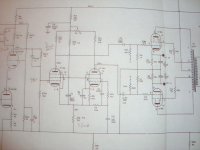
The 12BY7 is getting pricy. If you stay with LTP then there are loads of tubes around. These can be 6SN7, 6CG7 etc. The circuit of the Harmon Kardon is about the simplest LTP configuration.
Instead of the 12BY7, the sibling EF184 is cheaper and more available.
At present I cannot send pics as camera is xxx, but you can contact with me your fax num via members contact email.
richj
kimjul2005 said:For more than 10 years ago a copy( still not ready) of the TVA-1 was started to be build. I have two voltages to go for B+ 450V and B+ 560V. I hoped for approx. 70W with a sensitivity of approx. 1 to 1,5v.
The sensitivity is not critical - I have the Luxman C03 and several tube preamps to deliver more than 5 volt clean RMS.
You mention two B+ voltages: in Ultra Linear mode the 560V is out of the question for 6550 (whatever brand) but can take this in true pentode. Choose mode !
The ECF80 triode is rather nice, cheap with a low mu and makes an excellent concertina p/s. The pentode isn't screened and requires respect, microphony, hum etc, so I always use this in triode mode with line inputs.
Since you will have a high B+ (460+ will be required to get 70W), the direct coupling from input to driver tube isn't an issue.
If you use global nfb, a high pass LF roll-off in circuit is essential to correct for phase shift below o/p tranny cutoff.
The 12BY7 is getting pricy. If you stay with LTP then there are loads of tubes around. These can be 6SN7, 6CG7 etc. The circuit of the Harmon Kardon is about the simplest LTP configuration.
Instead of the 12BY7, the sibling EF184 is cheaper and more available.
At present I cannot send pics as camera is xxx, but you can contact with me your fax num via members contact email.
richj
Hi Rich Walters
Thank you again - I like the Ultra Linear mode, because of my experience from the last three tube amplifiers build. The sound was good , but on the other hand, I would like to have the increased power from the penthode mode.
For test , I think, I will choose the Ultra Linear mode.
I am happy for the suggested EF184 tube - I have some in stock!
Could the transmission by fax be done this way?
My friend at the Technical Institute offered me his fax number. If you send a fax this way, please write:
Att.: Mr. Claus Kjærgaard (or Kjaergaard)
the fax number is: + 45 (for Denmark) 45 88 71 33
Thank you very much , for your help in advance.
Best rgds. Kim
Kim, a couple of circuits faxed over.
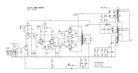
The STA100 Radford is an interesting arangement and may suit you well. The values of the feedback components will most likely differ if a foreign output tranny is used. Shown with KT88 outputs, UL operation at 600V is a heroic voltage.
hoope this helps.
richj
The STA100 Radford is an interesting arangement and may suit you well. The values of the feedback components will most likely differ if a foreign output tranny is used. Shown with KT88 outputs, UL operation at 600V is a heroic voltage.
hoope this helps.
richj
richwalters said:Kim, a couple of circuits faxed over.
The STA100 Radford is an interesting arangement and may suit you well. The values of the feedback components will most likely differ if a foreign output tranny is used. Shown with KT88 outputs, UL operation at 600V is a heroic voltage.
hoope this helps.
richj
can you send me scheme please?
please send to antonio<dot>tecson<at>kentech<dot>ie my yahoo mail does not work in my office.
thank you..
Hi Rich Walters
Thanks - I shall send you some details after having tested the circuit.
I looked for the EF184 - was lucky - had 6 pcs of Telefunken EF184 for test.
Ok - I will slow down the +B in UL operation - 60 watt or so will do it!
Thank you very much for writing back.
Sincerely yours
Kim
Thanks - I shall send you some details after having tested the circuit.
I looked for the EF184 - was lucky - had 6 pcs of Telefunken EF184 for test.
Ok - I will slow down the +B in UL operation - 60 watt or so will do it!
Thank you very much for writing back.
Sincerely yours
Kim
Test output trafo!
Hi,
Found a test trafo at : http://www.mennovanderveen.nl/eng/
from Vanderveen to be used for more than 20 circuits. The price is reasonable - 89 Euro - weight 4 kg.
A high performance toroid trafo to above 200kHz could be an option, if the amplifier turns out well in performance.
Rgds
Hi,
Found a test trafo at : http://www.mennovanderveen.nl/eng/
from Vanderveen to be used for more than 20 circuits. The price is reasonable - 89 Euro - weight 4 kg.
A high performance toroid trafo to above 200kHz could be an option, if the amplifier turns out well in performance.
Rgds
Re: Test output trafo!
Remember, be on your guard if copying a circuit from the past and expecting it to work with slick_modern output transformers, one could be in for nasty problems. The global nfb components may be wildest out, and amp may even oscillate within the o/p screen anode taps. This is one of the pitfalls of things going "pear shaped" when the global nfb is connected in UL work.
The EF184 and 12BY7 are flighty tubes designated for video and telecom respectively and have considerable u and ft in pentode mode.
richj
kimjul2005 said:
A high performance toroid trafo to above 200kHz could be an option, if the amplifier turns out well in performance.
Rgds
Remember, be on your guard if copying a circuit from the past and expecting it to work with slick_modern output transformers, one could be in for nasty problems. The global nfb components may be wildest out, and amp may even oscillate within the o/p screen anode taps. This is one of the pitfalls of things going "pear shaped" when the global nfb is connected in UL work.
The EF184 and 12BY7 are flighty tubes designated for video and telecom respectively and have considerable u and ft in pentode mode.
richj
Hi Rich Walters
Thank you for thinking about eventual problems with an old circuit and a modern output transformator.
The latest copy , the Leak Stereo 50, I made, featured some instability over 25 kHz because of the extended frequence range of the output transformers.
In order to turn the phase, we tryed to compensate with "lead lack" ( cap/resisor) over the plate resistor for the input tube - in this case the 6SL7 GT high mu tube. The result was a stabil amplifier with a -3 dB point at 56 kHz , by half power - approx. 13 Watt.
I like to use ordinary EI- iron transformers , as the audible frequence responce is more than sufficiant( for me). I know that the extended frequence area for ex. toroid o/p transformers may be a problem for amplifier stability. First of all we check out the curcuit performance - does it have a better sonic sound? and secondly - what can we achieve in frequence performance? - but the sonic sound is the more important issue. I like to think that the "soft" iron metal plates in outputtransformers gives a more smooth roll of( by experience- not messured).
I would very much like to hear the test amplifier with the EF184 drivers and the low thd. Up untill now I have only used triodes in the tubeamplifiers build, because I had the feeling, that penthodes for input and drivers were not a good solution( have been looking at many old and newer circuits).
At last - if we use fast transistors with high ft ( 30 mHz or more), some dc amplifiers even with/without FB gets unstable (again by experience) . I assume the same could happen with penthodes and high ft?
Again - thank you for taking action on this.
Best rgds
Kim
Re: Hi Rich Walters
Throwing the spanner in the works....Several decades ago I examined the Radford STA100 LTP phasesplitter for a specific circuit. Used in full pentode mode the gain on gain and volts on volts on paper it looked attractive but I found it performed poorly (when loaded) compared to the conventional concertina and a balanced Williamson push-pull voltage driver as shown in the 4 stage GEC 88 circuit.
Having setup the basic LTP Radford arrangement, (in pic) it gave 0.8% THD with a measly 25+25V rms output drive at 1Khz and 1% thd at 10Khz. In addition C7 on 2nd section LTP required tweaking to 100uF to avoid LF misbalance. All in all the Radford STA100 3 stage amp is a high flyer and replies on a high amount of global nfb (++30dB) to correct for circuit shortcomings to get thd down to 0.05% at only 60W o/p with a B+ of 600V. No thd figure given for the rated 100W or a dB under clipping which is my procedure.
My view is that tube HiFi amps should provide a distortionless output, right up onset clipping. The reason for this is soundly obvious.
During 1960-7, many designs adopted the LTP, the Mullard 20W is another example which relies alot on global nfb for stability against linearity. (Read up Morgan Jones Valve amps 3rd edit p.417). Alot of amps built around this period also had abysmal quality power supplies as electrolytic cap technology wasn’t fully developed.
I stopped doing more measurements when I came across a preamble note which claimed that amps using LTP and massiveamounts of global nfb for hi-fi, sounded duller than other phasesplitter configurations. This is a controversial topic found in many forums, made me think than those 1960 amps using LTP also had very good s/n ratio figures but sound quality was poor. At that time, anything was out to compete with emerging solid state amps.
To sum up,there are good LTP tube amp designs around 10-30W o/p around which use only modest amounts of global nfb, it is a fair comment to make to those enthusiasts who are new to tubing hifi amps, is start with a tame design without the full blooded +30dB global nfb, and get “fingers-on” with a simpler but excellent sounding Williamson (traditional concertina and push pull voltage driver) at the expense of poor s/n ratio and lower global nfb. The choice is out there. This is more likely to get one up and running . In the past 40 yrs I’ve debugged so many experimenters amps, owners who have copied a high flyer amp design, and without necessary knowledge and test/bench equipment is a recipe for dire trouble.
Stay simple unless one has the competence for a real adventure. The long and the short; anyone beavering with power amps should automatically do the math and keep notes to avoid doing silly mistakes.
Maybe the way forward is to try these power LTP circuits with a CCS in the cathode tail and see how they (brilliantly) perform. It does seem strange that this technique wasn’t adopted on the day, some 45+yrs ago.
richj
kimjul2005 said:
The latest copy , the Leak Stereo 50, I made, featured some instability over 25 kHz because of the extended frequence range of the output transformers.
I would very much like to hear the test amplifier with the EF184 drivers and the low thd. Up untill now I have only used triodes in the tubeamplifiers build, because I had the feeling, that penthodes for input and drivers were not a good solution( have been looking at many old and newer circuits).
Best rgds
Kim
Throwing the spanner in the works....Several decades ago I examined the Radford STA100 LTP phasesplitter for a specific circuit. Used in full pentode mode the gain on gain and volts on volts on paper it looked attractive but I found it performed poorly (when loaded) compared to the conventional concertina and a balanced Williamson push-pull voltage driver as shown in the 4 stage GEC 88 circuit.
Having setup the basic LTP Radford arrangement, (in pic) it gave 0.8% THD with a measly 25+25V rms output drive at 1Khz and 1% thd at 10Khz. In addition C7 on 2nd section LTP required tweaking to 100uF to avoid LF misbalance. All in all the Radford STA100 3 stage amp is a high flyer and replies on a high amount of global nfb (++30dB) to correct for circuit shortcomings to get thd down to 0.05% at only 60W o/p with a B+ of 600V. No thd figure given for the rated 100W or a dB under clipping which is my procedure.
My view is that tube HiFi amps should provide a distortionless output, right up onset clipping. The reason for this is soundly obvious.
During 1960-7, many designs adopted the LTP, the Mullard 20W is another example which relies alot on global nfb for stability against linearity. (Read up Morgan Jones Valve amps 3rd edit p.417). Alot of amps built around this period also had abysmal quality power supplies as electrolytic cap technology wasn’t fully developed.
I stopped doing more measurements when I came across a preamble note which claimed that amps using LTP and massiveamounts of global nfb for hi-fi, sounded duller than other phasesplitter configurations. This is a controversial topic found in many forums, made me think than those 1960 amps using LTP also had very good s/n ratio figures but sound quality was poor. At that time, anything was out to compete with emerging solid state amps.
To sum up,there are good LTP tube amp designs around 10-30W o/p around which use only modest amounts of global nfb, it is a fair comment to make to those enthusiasts who are new to tubing hifi amps, is start with a tame design without the full blooded +30dB global nfb, and get “fingers-on” with a simpler but excellent sounding Williamson (traditional concertina and push pull voltage driver) at the expense of poor s/n ratio and lower global nfb. The choice is out there. This is more likely to get one up and running . In the past 40 yrs I’ve debugged so many experimenters amps, owners who have copied a high flyer amp design, and without necessary knowledge and test/bench equipment is a recipe for dire trouble.
Stay simple unless one has the competence for a real adventure. The long and the short; anyone beavering with power amps should automatically do the math and keep notes to avoid doing silly mistakes.
Maybe the way forward is to try these power LTP circuits with a CCS in the cathode tail and see how they (brilliantly) perform. It does seem strange that this technique wasn’t adopted on the day, some 45+yrs ago.
richj
Attachments
Hi Tony
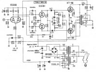
As promised the two circuits I received from Mr. Rich Walters. I have been looking through my own schematics and found the mentioned circuits in the database.
1 Radford STA100 and 2. Harmon kardon V
Rgds Kim
Tony said:
can you send me scheme please?
please send to antonio<dot>tecson<at>kentech<dot>ie my yahoo mail does not work in my office.
thank you..
As promised the two circuits I received from Mr. Rich Walters. I have been looking through my own schematics and found the mentioned circuits in the database.
1 Radford STA100 and 2. Harmon kardon V
Rgds Kim
Attachments
- Status
- This old topic is closed. If you want to reopen this topic, contact a moderator using the "Report Post" button.
- Home
- Amplifiers
- Tubes / Valves
- 6550a question for engineer?