I have an old LP12 -- from 1974. A couple years ago I put a "nice" cartridge on it (some Clearaudio thing that cost too much), which broke after about a year of light use. So, after not listening to any of the gems in my record collection in a long time, I am now going to put a cheap cartridge on it, probably a Shure M97xE unless someone has a better $50 option. But I need a phonostage.
Any suggestions? I like the look of Thorsten's (12AX7 into 6922) and it seems simple enough, and I think I have all the parts necessary to build a cheapo version, but people seem to badmouth the 12ax7 for phono input duty. I have a really good stash of 6SL7's and 6SN7's that I am never going to use for anything else, so I wouldn't mind using them here. I also have several lifetime supplies of 6688's and 5879's so a pentode stage would not be out of the question.
Any particular circuit suggestions, or online tools for calculating RIAA curves? Also, this is going to have to push longish (15 foot) cables with a TVC on the other end. I do want to do tubes and stay away from opamps, but a mosfet follower on the output is an option. Cathode follower is probably fine as well, or a grounded cathode if rp is low enough.
My two pence:
http://www.dissident-audio.com/RIAA_PC900/Page.html
But build it larger than I've done, each channel dissipates near 10 Watts including heaters
Not to tell about regulators efficiency")
Yves.
http://www.dissident-audio.com/RIAA_PC900/Page.html
But build it larger than I've done, each channel dissipates near 10 Watts including heaters
Not to tell about regulators efficiency
Yves.
My understanding is that the 12AX7 is a bad front-end tube due to its high input capacitance. Given that what you're going for here is total gain, what's the problem with using a 6922 as your input tube and moving the 12AX7 behind it, where it won't load the cartridge excessively?
dsavitsk said:I have an old LP12 -- from 1974. A couple years ago I put a "nice" cartridge on it (some Clearaudio thing that cost too much), which broke after about a year of light use. So, after not listening to any of the gems in my record collection in a long time, I am now going to put a cheap cartridge on it, probably a Shure M97xE unless someone has a better $50 option. But I need a phonostage.
Any suggestions? I like the look of Thorsten's (12AX7 into 6922) and it seems simple enough, and I think I have all the parts necessary to build a cheapo version, but people seem to badmouth the 12ax7 for phono input duty. I have a really good stash of 6SL7's and 6SN7's that I am never going to use for anything else, so I wouldn't mind using them here. I also have several lifetime supplies of 6688's and 5879's so a pentode stage would not be out of the question.
Any particular circuit suggestions, or online tools for calculating RIAA curves? Also, this is going to have to push longish (15 foot) cables with a TVC on the other end. I do want to do tubes and stay away from opamps, but a mosfet follower on the output is an option. Cathode follower is probably fine as well, or a grounded cathode if rp is low enough.
Dude,
The objection to high mu/high RP types at a phono preamp's I/P is the potential for frequency response trouble, due to cartridge/Miller capacitance interaction. Some MM level carts. are fine working into an 'X7, while other carts. do poorly.
A variation on the RCA passive RIAA EQ theme should do the job for you. To make 100% certain that Miller capacitance is not an issue, use 6GK5s in the 1st gain block positions. Talk to your "neighbor", Jim McShane about 6GK5s.
KAB provides a passive RIAA EQ calculator. Look here.
Thorsten's design lacks the drive necessary for your situation. AAMOF, you have an especially difficult setup. Interconnect cables that are 15 feet long MUST be shielded. You need a phono preamp whose O/P impedance is LOW and whose drive current is HIGH, to deal with cable capacitance and the TVC. I suggest you use 6GK5 1st gain blocks, grid leak biased 6SL7 2nd gain blocks working into DC coupled 6SN7 cathode followers. The 'SN7 CFs have the "sock" needed to drive IRFBC20 source followers. Run the FETs at ID = 20 mA. Good bye to drive capability issues. Use a 9 V. Lithium battery in each channel to forward bias the gates. Since a high gate resistor value is not problematic, use a highly transparent PTFE dielectric coupling cap. of modest value between the 'SN7 and the FET. My guess is that a bypassed 10 μF. motor run cap. will be needed between the FET and the O/P RCA female.
Re: Re: Yet Another Phono Stage Suggestions Thread
Interesting, looks like a good tube to use here. Maybe these in conjunction with 6T4's for an all 7 pin project.
Thanks. Very useful. R1 in the equation should be the resistor (R1') used in series with the Zo from the first stage?
Eli Duttman said:A variation on the RCA passive RIAA EQ theme should do the job for you. To make 100% certain that Miller capacitance is not an issue, use 6GK5s in the 1st gain block positions. Talk to your "neighbor", Jim McShane about 6GK5s.
Interesting, looks like a good tube to use here. Maybe these in conjunction with 6T4's for an all 7 pin project.
Eli Duttman said:KAB provides a passive RIAA EQ calculator. Look here.
Thanks. Very useful. R1 in the equation should be the resistor (R1') used in series with the Zo from the first stage?
an excellent phono stage... I built it and sub'd ecc35 for the 5751's
You could also sub in 6SL7's for the 417a and 5751.
Is a Mu stage WE417a input and a Mu stage 5751 output with a passive RIAA eq in between.
There is no mistake in the schemo.... there is no grid stopper into the 417a..... designer says 417a is very happy without and one less resistor for the signal to pass through.
I used Allen Wrights SuperReg in the power supply
here's his PCB version with designers notes:
http://www.dddac.de/tp06.htm
here's the hardwaire version:
http://www.dddac.de/tp07.htm
JD
A1 gain ...
Hi,
I am sure you don't want to know that A1 gain should exceed 40dB.
Kind regards,
Darius
dsavitsk said:...
Thanks. Very useful. R1 in the equation should be the resistor (R1') used in series with the Zo from the first stage?
Hi,
I am sure you don't want to know that A1 gain should exceed 40dB.
Kind regards,
Darius
Re: Re: Re: Yet Another Phono Stage Suggestions Thread
Yes you need to include the preceding stage's rp in the total. Also to reduce sensitivity to variations in rp due to operating point, aging, and initial tube tolerances it is a good idea to make R1 several times larger than rp at minimum - with very low rp tubes you can make it much greater without exacting a huge noise penalty. Don't neglect the johnson noise generated by both the rp of the preceding tube and R1 - try to choose a high mu tube with a low rp for this reason. (Seems like triode connected 6688 might be good in this location as is the 5842/417A, or triode connected D3A or 7788.) FWIW I am a huge fan of the D3A in triode connection for this task.
All of my phono stages use this basic topology and the passive equalization is based on the work of Stanley Lipshitz (U of Ontario) who deserves to be mentioned when this eq network comes up.
I aim for as high mu as I can get in that first stage, and as few active stages overall that I can manage. (Just 2 currently) Gain in my first stage is about 37dB - not quite the 40dB that Darius recommends.
dsavitsk said:
<snip>
Thanks. Very useful. R1 in the equation should be the resistor (R1') used in series with the Zo from the first stage?
Yes you need to include the preceding stage's rp in the total. Also to reduce sensitivity to variations in rp due to operating point, aging, and initial tube tolerances it is a good idea to make R1 several times larger than rp at minimum - with very low rp tubes you can make it much greater without exacting a huge noise penalty. Don't neglect the johnson noise generated by both the rp of the preceding tube and R1 - try to choose a high mu tube with a low rp for this reason. (Seems like triode connected 6688 might be good in this location as is the 5842/417A, or triode connected D3A or 7788.) FWIW I am a huge fan of the D3A in triode connection for this task.
All of my phono stages use this basic topology and the passive equalization is based on the work of Stanley Lipshitz (U of Ontario) who deserves to be mentioned when this eq network comes up.
I aim for as high mu as I can get in that first stage, and as few active stages overall that I can manage. (Just 2 currently) Gain in my first stage is about 37dB - not quite the 40dB that Darius recommends.
Guys,
I frankly have trouble mapping KAB's diagram onto a real world circuit, like this. AAMOF, R6 should be 255 KOhms, not 470 KOhms. The 20 MOhm value for R2, instead of 680 KOhms in a "stock" RCA circuit, forces that change. Clearly, interactions are present. Yet another issue is properly sizing the coupling cap. between the 1st gain block and the EQ network. Should the value remain 100 nF.?
Noise considerations make the use of a Caddock part in the 20 M position close to mandatory. If an assault on near SOTA performance is to be attempted, I can see using a Vishay bulk metal foil part for R1 in the KAB diagram.
Eli Duttman said:Guys,
I frankly have trouble mapping KAB's diagram onto a real world circuit, like this. AAMOF, R6 should be 255 KOhms, not 470 KOhms. The 20 MOhm value for R2, instead of 680 KOhms in a "stock" RCA circuit, forces that change. Clearly, interactions are present. Yet another issue is properly sizing the coupling cap. between the 1st gain block and the EQ network. Should the value remain 100 nF.?
Noise considerations make the use of a Caddock part in the 20 M position close to mandatory. If an assault on near SOTA performance is to be attempted, I can see using a Vishay bulk metal foil part for R1 in the KAB diagram.
That's understandable.. Not IMHO near the best implementation I've of this circuit that I have seen. I generally place the grid bias resistor for the following stage before R1, and choose network values that keep the overall effective bias resistance below that recommended for the type in question. Yes grid bias current does flow through R1 in this scenario, but so far I have not observed any noise related issues and placing the resistor ahead of the EQ network eliminates its effect on the network.
A 0.1uF coupling is a bit marginal once R1 drops below about 300K or so, the pole interacts with the lowest pole in the RIAA EQ and causes a premature roll-off in the low end and hence the accuracy of the LF EQ . Choose too small of a value and you can inadvertently get quite close to the IEC modified playback response and if you have a rumbly TT this might actually be useful. Otherwise make the -3dB corner at least a decade lower than the 50Hz RIAA turnover point.
kevinkr said:
A 0.1uF coupling is a bit marginal once R1 drops below about 300K or so, the pole interacts with the lowest pole in the RIAA EQ and causes a premature roll-off in the low end and hence the accuracy of the LF EQ . Choose too small of a value and you can inadvertently get quite close to the IEC modified playback response and if you have a rumbly TT this might actually be useful. Otherwise make the -3dB corner at least a decade lower than the 50Hz RIAA turnover point.
Once my amp spit off a cone of a woofer with a piezoelectric crystal glued to it (feedback by acceleration) trying to follow output from a vinyl with a bit shifted center hole.
Wavebourn said:
Once my amp spit off a cone of a woofer with a piezoelectric crystal glued to it (feedback by acceleration) trying to follow output from a vinyl with a bit shifted center hole.
Literally wow...

kevinkr said:
Literally wow...
That's why I implement HPF even in bass guitar amps.
Here's a first go incorporating some of the ideas from the thread. I don't know what mosfet to use, or how to calculate the resistor under it, so that's the next thing to figure out. B+ probably will be ~120V or so, though as low as ~90V should be fine.
Thoughts?
Thoughts?
Attachments
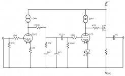
Use one with a lowish Cdg.
To figure the resistor, assume that the source voltage will be within a volt of two of the gate voltage. The gate voltage will be equal to the plate voltage of the 6T4. So the resistor will be that voltage divided by the desired operating current.
To figure the resistor, assume that the source voltage will be within a volt of two of the gate voltage. The gate voltage will be equal to the plate voltage of the 6T4. So the resistor will be that voltage divided by the desired operating current.
dsavitsk said:Here's a first go incorporating some of the ideas from the thread. I don't know what mosfet to use, or how to calculate the resistor under it, so that's the next thing to figure out. B+ probably will be ~120V or so, though as low as ~90V should be fine.
Thoughts?
Dude,
Assuming you get close to full mu gain from the CCS loads, you come up (IMO) a bit short in the net gain dept., using the 6T4 in the 2nd gain position. Expect somewhat less than 40 dB. net, in the real world.
The IRFBC20 I previously mentioned will be fine in the source follower role. A FET with a low and stable reverse transfer capacitance is required. Check the IRFBC20 data sheet out.
Eli Duttman said:Assuming you get close to full mu gain from the CCS loads, you come up (IMO) a bit short in the net gain dept., using the 6T4 in the 2nd gain position. Expect somewhat less than 40 dB. net, in the real world.
Input sensitivity on my power amps is about 1.5V, and I never listen anywhere near that level. So, I think I should be fine. But, the 6Gk5 and 6t4 have the same pin out, so I can just dial back the current in the second tube and drop in a 6GK5 if necessary.
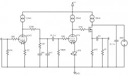
Here's a slightly more complete schematic.
Attachments
- Status
- This old topic is closed. If you want to reopen this topic, contact a moderator using the "Report Post" button.
- Home
- Amplifiers
- Tubes / Valves
- Yet Another Phono Stage Suggestions Thread