I just acquired from a yardsale a Masco MA-17 N PA amplifier, a push-pull 6L6 amp. The Masco is in working condition, but horribly noisy due to age of parts, etc. Keeping the chassis, iron, and tubes, I would like to rebuild this into a decent mono amplifier.
The tubes on the amp are:
5V4G
6SC7
6SJ6
6SL7GT
6L6G x 2
The current configuration is rather complicated, with inputs for two microphones and phono, along with bass and treble controls. I don't need these features or complexity.
Does anyone have schematics for an amplifier using these parts? I would prefer designs with a fairly low budget: all parts not much over the $25 Digikey minimum order. It would be especially nice to have an amp that would allow me to switch between push-pull class A and class AB for more power.
Thank you.
-Michael
PA amps can make great guitar amps - but the output iron is not usually the best for high fidelity. But doesn't sound like you're planning to put a lot into it, so you can definitely get your money's worth. Plan on new caps - the old ones are leaky, for sure.
First, how much power are you looking for? Triode mode will give maybe 10 Watts, but calls for a heftier driver like 6SN7. I'd prefer the 6SN7 in any case, but the 6SL7 will do. So will the 6SC7, which is about the same, but with both cathodes tied together - perfect for a long-tail phase inverter. Something like the Eico HF-22 maybe?
HF-22
Depends on what you are trying to do. If you only want an instrument amp, just replace all the caps and any dud resistors, and crank the volume. 
If you want to make it hi-fi, you may need to rebuild the circuit to a new design (not too hard at all.) If you are not using a microphone or turntable you won't need half those tubes, a 6SN7 and 2 6L6 plus 5v4 will be enough.
The good thing about that amp is that it will have a fair bit of capacity, it could be great just for parts etc.
phonon said:Keeping the chassis, iron, and tubes, I would like to rebuild this into a decent mono amplifier.
If you are keeping the output tranny you are limited in making alterations to the output stage in terms of increasing output or improving quality. If you replace the electrolytics as suggested you may find that you can make use of the high gain of the amp by increasing the amount of negative feedback to try to overcome some of the limitations of the output tranny. Acceptable quality might be achievable without too many circuit alterations.
I'm not trying to make this into a super-high-fidelity amp, so the existing output transformer is fine; it can go up to 20kHz without too much attenuation, and goes down to as low frequencies as my (small) speakers can handle.
I intend to use this amplifier for listening to some of my older mono records, which are not very bandwidth demanding anyway.
As far as power goes, the amp currently has far more than I actually need; 10 W or more would be enough. Although I am using rather inefficient speakers, I am in a small room and I don't usually listen at high levels.
I've already augmented the filter capacitors with some slightly newer ones pulled from other equipment, and this has completely fixed the 60 Hz hum problem, but the amp still has a lot of random noise at all frequencies.
This is my first time building a tube amp, so please be generous with the schematics so that I know what you are talking about. I may even want to rebuild this amp several times to learn some of the different topologies. Since I have the high-gain tubes available, it would be nice to be able to run the amp either directly from my turntable (MM cartridge) and avoid solid-state electronics completely, or from line level out of my preamp.
(Correction to first post typo: one of the tubes is a 6SJ7, not a 6SJ6)
Thank you.
-Michael
Micheal,
Many of the schematics on the web use 6L6s in ultra-linear configuration - does the output tranny you use have tappings for this kind of operation? For a more conventional circuit check this at the Heathkit virtual museum:
http://www.heathkit-museum.com/hifi/a-9c.shtml
This amp uses normal loading in the output stage, but 12AU7s/12AX7s in the other stages - if you have a 6SN7 as opposed to your 6SL7 this could be used as the driver/phase splitter instead of the 12AU7 in the circuit.
The Heathkit circuit should also give you some ideas on a pre-amp stage for a MM cartridge.
Bouneville,
what kind of transformer tappings do you especially need for the ultralinear configuration? My transformer has a center-tapped primary, and secondaries for six different output impedences. If my transformer will work, can you direct me to a schematic for a 6L6/6SL7 ultralinear amp? I don't want to buy different tubes, and I already have four extra 6SL7 tubes sitting around. A phono stage is highly optional, and I should probably wait to add it on until after I have a working line-level amplifier.
Thank you.
-Michael
Photos, please.
Many of those older LPs were gloriously recorded so it's worth making an effort with this amplifier. You could [b[probably[/b] build the RIAA stage into the amplifier, but you would need to be very good at construction to do so without hum creeping in. If you strap the output valves as triodes, you ought to be able to get ten quite good quality watts out of it.
Regarding your actual new circuit. It would help greatly if you could post some photographs of the amplifier (top and underneath) so that we can see what you have to work with.
photos II
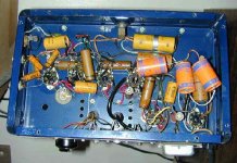
The top of the amp.
The six tubes on the amp represent five different manufacturers; the two 6L6 output tubes are in different shaped glass enclosures.
Left to right tubes in the picture:
Tung-Sol 6SC7
Ken-Rad 6SJ7
Tung-Sol 6SL7GT
RCA 6L6GC
Sylvania 6L6G
GE 5V4GA
The top of the amp.
The six tubes on the amp represent five different manufacturers; the two 6L6 output tubes are in different shaped glass enclosures.
Left to right tubes in the picture:
Tung-Sol 6SC7
Ken-Rad 6SJ7
Tung-Sol 6SL7GT
RCA 6L6GC
Sylvania 6L6G
GE 5V4GA
Attachments
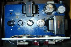
Great! A picture certainly is better than a thousand words. The output transformer is rather small, and nothing to write home about. The amplifier looks quite old, judging by the cotton covered wiring, which doesn't bode well for output transformer quality. The chassis is a decent size, so there's plenty of room to bash another hole or two for another valve. Given the size, it may be possible to make RIAA work without hum. The mains transformer looks a reasonably healthy size, so there ought to be adequate current available. The heater wiring is, as usual, terrible, which is why a hundinger pot was needed. A goodly proportion of the passive components are likely to be faulty, the capacitors will have let air in, so electrolytics will be low value, and paper will be leaky. The carbon resistors could well have gone high in value.
All in all, what you have is a chassis with the metalwork done for you that has transformers bolted to it, and a collection of valves. Otheres will probably disagree violently, but I would trace out the circuit of the existing amplifier, then rip out all the wiring and components and start again. I would use new valve bases. To add RIAA, a B9A base will probably be needed at the far end of the chassis in line with the other valves.
Now all that has to be decided is the circuit. (And your willingness to build it.)
phonon said:Bouneville,
what kind of transformer tappings do you especially need for the ultralinear configuration? My transformer has a center-tapped primary, and secondaries for six different output impedences.
For ultra-linear operation your transformer would need tappings on the primary for the screen grids as well - 20% or 43% are recommended for particular circuits - so you are limited to a circuit like the Heathkit amp, possibly paralleling one of your 6SL7s as the phase splitter to provide greater power handling capability instead of half a 6SN7.
However, having seen the amp and bearing in mind some of EC8010's comments, if you stick only with the existing parts (including the small output tranny and the unmatched 6L6s) it would be difficult to build a better amp with these parts than your current (working) one, so it may be better to tinker with the existing circuit, such as increasing the NFB, removing unnecessary pre-amp stages etc...
EC8010 said:judging by the cotton covered wiring, which doesn't bode well for output transformer quality.
I sort of agree, but I have some Dyna Z565 OPTs which have cloth covered leads, and they're excellent. I also have some locally made (A&R or Ferguson?) OPTs that look similar, but have performed OK in quick tests, much better than the visuals would indicate. Not great, but would make a great 5W PP office amp.
The heater wiring is, as usual, terrible, which is why a hundinger pot was needed.
It doesn't look much like an old Tek or HP in there does it? But not unusual IME.
All in all, what you have is a chassis with the metalwork done for you that has transformers bolted to it, and a collection of valves. Otheres will probably disagree violently, but I would trace out the circuit of the existing amplifier, then rip out all the wiring and components and start again. I would use new valve bases.
I'm with you. I've done a couple of resto's like this before, and they can be a huge PITA. I have a Fisher 800B reveiver that's partially done, but I put away as I became frustrated with it. When one faulty part was exchanged, other old parts would show their deficiencies, and I'd need to open it up the change something else. I've resisted wholesale resistor subs because it blows it's collector value, but I'm tempted to just replace everything with Kiwames and modern poly caps and be done with it. Luckily for me, the tuner section was professionally aligned before I bought it, and is stable.
The Lowthers I bought recently are even worse, even though the design and layout is much better. I'll use the iron in other amps, store the leftovers, and restore them properly when I retire in 30 years or so.
Use it as parts, design a new circuit, build it well, and enjoy a reliable amp for years to come.
I have been tracing out the circuit, making some progress in understanding what it is doing. I just sent off a digikey order for parts to replace all the resistors and capacitors. For now I will keep the original design for the line-level and output stages.
The "phono" input has plenty of gain for line-level amplification. There are also two microphone inputs, additionally amplified by the 6SC7 for extra gain. It seems that by feeding the output of one side of the 6SC7 back into the input of the other side, I should be able to get very high gain, enough for preamplifying a MM cartridge. What kind of R/C networks could I put in a 2-stage preamplification circuit using the 6SC7 to get approximate RIAA equalization?
The "phono" input has plenty of gain for line-level amplification. There are also two microphone inputs, additionally amplified by the 6SC7 for extra gain. It seems that by feeding the output of one side of the 6SC7 back into the input of the other side, I should be able to get very high gain, enough for preamplifying a MM cartridge. What kind of R/C networks could I put in a 2-stage preamplification circuit using the 6SC7 to get approximate RIAA equalization?
Active or passive?
The right ones. We don't do "approximate" here. If you can sketch out the diagram, add all DC voltages, scan and post it, RIAA values can be calculated properly.
phonon said:What kind of R/C networks could I put in a 2-stage preamplification circuit using the 6SC7 to get approximate RIAA equalization?
The right ones. We don't do "approximate" here. If you can sketch out the diagram, add all DC voltages, scan and post it, RIAA values can be calculated properly.
The right ones. We don't do "approximate" here. If you can sketch out the diagram, add all DC voltages, scan and post it, RIAA values can be calculated properly.
Here is the schematic for the microphone gain stage (the other mic. input is exactly like this one, using the other half of the 6SC7). I should be able to turn the two mic inputs into a single high-gain stage just by re-wiring the output of one side of the 6SC7 to the input of the other?
If higher voltages are needed, I can get up to 285V at the rectifier output (but less well filtered).
Attachments
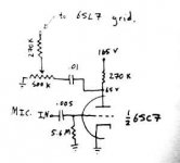
I see that grid potential is rising from a high value grid leak and a grounded cathode. Although this is fine for a mike input stage (it has the advantage of providing a high input impedence for crystal mikes) from a quality point of view it leaves much to be desired - you need to consider a smaller grid resistor and using cathode bias. Using grid bias was common in cheaper valve tape recorder input stages and occasionally old valve radios, but while giving good gain it does not amplify in a linear fashion, at the very least you would need to use NFB to improve the quality for a hifi amp.
If you feed one input stage into the other I think that the high gain will give you instability problems, unless you take measures to reduce gain and provide more/better decoupling.
If you feed one input stage into the other I think that the high gain will give you instability problems, unless you take measures to reduce gain and provide more/better decoupling.
I just tried connecting the mic gainstages in series. Bournville, you are right that without attenuation between the stages, the result is horrible instability. However, by including the volume pot between the two stages, I am able to adjust the gain to a working value. The amplifier is currently playing directly from my turntable (although it doesn't sound too good, since I don't have any RIAA compensation).
Since I am new to tubes, could you please post a schematic with values showing what you are suggesting with regard to improving the input stage? Would using a 50k or so reisistor instead of the 5M one, and moving the 270k resistor and output from the plate to the cathode be doing what you are saying?
Thank you.
Regrets that I don't have the ability on my current system to post a schematic, but I think there are one or two things you could try with the input stage from the MM cartridge. First of all, to use cathode bias you need to cut the direct connection from cathode to ground and insert a resistor connecting the cathode to ground instead, 2.2k would seem a reasonable value and it can be bypassed by an electroytic of 25-50uf (although this could be missed out to allow degenerative NFB). Since the MM cartridge is much lower impedence than a crystal mike you can drop the grid resistor to 47-100k and you need to replace the 0.005uf cap with something more substantial to increase bass response, perhaps 1uf or similar. I should leave the anode resistor value as it is, but replace the 0.01uf with a larger value, 0.1uf or similar to also increase bass response.
These are rough and ready values but should work ok in your schematic.
These are rough and ready values but should work ok in your schematic.
- Status
- This old topic is closed. If you want to reopen this topic, contact a moderator using the "Report Post" button.
- Home
- Amplifiers
- Tubes / Valves
- rebuilding 6L6 amp ... suggestions?