Hi all,
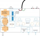
Before I drill and fill my chassis I was hoping to run a layout diagram by those with experience. It's a 10x17x3" aluminum box. Unfortunately my Aikido board is slightly too long to fit in front to back if that is potentially recommended. All parts are drawn to scale. Orange components sit on top, blue inside. I have arranged keeping in mind the following criteria:
- Keep high and low voltage as far apart as possible
-Cross AC and DC lines perpendicularly rather than along side each other
-Mount adjacent transformers/chokes at different orientations
Any suggestions are welcome and appreciated.
Thanks,
gary
Attachments
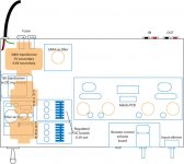
I'll second the line cord to the far left corner. I woiuld also put the 5AR4 toward the rear closer to the power transformer which keeps it further from the signal tubes as well as keeping the HV wiring short and tucked close to the rear of the chassis. Then bring the filament regs forward since they radiate less, if at all.
Victor
Victor
- Status
- This old topic is closed. If you want to reopen this topic, contact a moderator using the "Report Post" button.