
I think that method is described in detail here:
http://www.aikenamps.com/BackBiasing.html
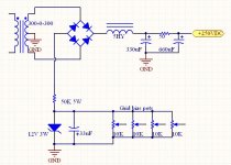
Scroll down to the middle of the page to see a similar schematic.
http://www.aikenamps.com/BackBiasing.html
Scroll down to the middle of the page to see a similar schematic.
It will work, and I have done similar things in the past, but I wouldn't do it this way now for the following reasons:
I'd use a small 12V - 15V transformer with a bridge rectifier and CRC filter and the pots instead - more reliable, less heat and mostly addresses last concern listed above.
- Lots of power dissipation in that resistor depending on load current.
- Zener goes open and you end up with more than -50V across that cap.
- Not a good idea to regulate grid bias in an amplifier with unregulated plate or screen supplies. To some extent properly designed amplifiers with unregulated plate/screen supplies and unregulated bias supplies will compensate for significant variations in mains supply voltage, regulate one without the other and this is no longer the case.
I'd use a small 12V - 15V transformer with a bridge rectifier and CRC filter and the pots instead - more reliable, less heat and mostly addresses last concern listed above.
andyjevans said:What's the problem in case of failure?
If the input resistor dies, you lose bias and the output tubes die. Use a wirewound resistor here for reliability.
If the zener fails, the tubes get full negative and cutoff.
Don't use cheap bias pots, use wirewound here too (a 1W-5W wirewound is cheaper than a 1/2W DC rated carbon).
Cheers!
Don't use cheap bias pots, use wirewound here too (a 1W-5W wirewound is cheaper than a 1/2W DC rated carbon).
Are those small blue multi turn pots any good? Because thats what I planned on using
 The screen supply will be regulated using this schematic http://www.antiquewireless.org/otb/resto0504.htm
I probably will end up using separate transformer to run the relays and other control circuits anyhow. As of right now my plan is to use a quad comparator monitoring each 10 ohm cathode resistor. If any tube goes over the limit it makes an input to the PIC chip go high which shuts off the B+ relay and lights an LED.
Hi,
The Bourns ones I've used, yes. They are either WW, conductive plastic (3/4W+) or DC rated carbons (<=1/2W).
Just tie the wiper so that if it opens, the tubes see greater -V than ground.
Cheers!
astouffer said:
Are those small blue multi turn pots any good? Because thats what I planned on using
The Bourns ones I've used, yes. They are either WW, conductive plastic (3/4W+) or DC rated carbons (<=1/2W).
Just tie the wiper so that if it opens, the tubes see greater -V than ground.
Cheers!
astouffer said:
Are those small blue multi turn pots any good? Because thats what I planned on using
I probably will end up using separate transformer to run the relays and other control circuits anyhow. As of right now my plan is to use a quad comparator monitoring each 10 ohm cathode resistor. If any tube goes over the limit it makes an input to the PIC chip go high which shuts off the B+ relay and lights an LED.
I recommend the hot molded carbon, hermetically sealed, 2W Clarostat, Bourns, or Ohmite or similar RV4LAYSA locking style pots - in over 20yrs these have never let me down, and I've had old tube Marantz and other hifi gear that used these and so far I've yet to see a bad one, they just seem to last forever. I think the Clarostats are available either at Mouser or Digikey - Digikey's prices are a lot better on these however.
Use a 100K resistor between the wiper and the hot end for insurance in the event that the pot wiper ever goes open. (I don't bother, but frankly I do know better, do as I say, not as I do..
)Regulated screens with regulated bias should be the cat's meow, but for even better stability replace that zener (which will drift a bit as it warms up) with a low cost precision voltage regulator..
Also add a resistor from the bottom end of the pot in series to ground so that you cannot adjust the pot to 0 bias, preventing some serious mishaps. Multi-turn pots are very fiddly and the resolution is not required.
Zener goes open and you end up with more than -50V across that cap..... If the zener fails, the tubes get full negative and cutoff.
My experience (I have blown up a lot of parts) says that zeners usually fail to a short, unless a bunch of current was available to blow it open.
The point about regulating the bias without regulating the plate (triode) or screen (pentode) is very valid. I use a similar design in the Tubelab SE without the zener. I use a resistive divider which does waste some energy but works well.
tubelab.com said:
My experience (I have blown up a lot of parts) says that zeners usually fail to a short, unless a bunch of current was available to blow it open.
The point about regulating the bias without regulating the plate (triode) or screen (pentode) is very valid. I use a similar design in the Tubelab SE without the zener. I use a resistive divider which does waste some energy but works well.
Usually my experience too, and of course the short scenario is worse for the output tubes than the reverse situation, but operated well within ratings neither scenario is very likely after the first few hours of operation. My most memorable problem with a zener was actually an open, and yeah the cap across it blew up..
 Never happened since..
- Status
- This old topic is closed. If you want to reopen this topic, contact a moderator using the "Report Post" button.
- Home
- Amplifiers
- Tubes / Valves
- Bias supply idea