I have my DIY bass amp head all tuned up and sounding good and very loud. It was inspired by the 300W Fender 300PS but is there any way short if a boatload of expensive instruments to determine the actual power output capability? Can it be calculated?
This is kind of like when I had my '68 GTO dynoed. I was sure that street/strip 455 was going to put me into the 400HP bracket. But instead, I had 265 HP on the floor.
Thanks
This is kind of like when I had my '68 GTO dynoed. I was sure that street/strip 455 was going to put me into the 400HP bracket. But instead, I had 265 HP on the floor.
Thanks
Sure. P=I*V and V=I*R. Therefore, I=V/R and P=(V^2)/R.
Get a sine generator. Hook it up to the input of your amp. Connect a known load to the output, probably an 8 ohm dummy load made out of sufficient quantity of cemented resistors to handle the expected output power.
Connect your oscilloscope across the dummy load, power everything up, and watch the waveform. Slowly increase the gain until you observe signs of clipping (peaks start to flatten) or any other unwarranted distortion. At this point, read the voltage from the zero line to the peak of the sine wave. This is your peak voltage. Divide by the square root of two (1.414) to account for the area under the curve of the sine function. Take the result, square it, and divide by the load resistance. This is your output power.
If you are hoping to get 300 watts out of the thing, you'll need to see just under 70 volts zero to peak driven into an 8 ohm load.
Rodango said:I have a huge 6.8 ohm and a huge 10 ohm resistor. Would either of those be acceptable? The amp has an 8 ohm output.
Thanks!
Yes, either will do. Pick the one closest to your expected use conditions. Ty's method is fine. If you have a true RMS multimeter, it's easier to read the output voltage directly from that, instead of the scope screen. You'll still want the scope to look for clipping onset.
Sheldon
edit: BTW, as long as you are at it, make note of the signal generator level that you use for your output measurement. I like to record this, so that I know amplifier gain. Comes in handy when you want to substitute amps.
"I have a huge 6.8 ohm and a huge 10 ohm resistor. Would either of those be acceptable?"
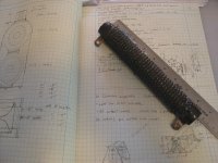
Depends on what you mean by huge. Here is a picture of a 300 watt
resistor. This is a compact one. I use this type for dummy loads
because they're rugged and cheap. They also have an optional
sliding contact you can use to get smaller resistance values. I
use a 10 ohm with the contact that allows me to set to 8.0 ohms.
This reduces the power rating of the resistor correspondingly.
Also, as these heat up the resistance increases; I don't know
how much because I run them cool.
That amp is like an Ampeg SVT, right? Might be worth trying both
6.8 and 10R loads to see what you get. Real speakers will vary
with frequency anyway, and what you have is probably about the
right range for an 8 ohm instrument speaker.
Cheers,
Michael
Attachments

You appear to have serious crossover distortion. That may help it sound loud.
The crossover distortion may not be a serious as it seems.
If you overdrive output tubes they will draw grid current. The grid current will overcharge the grid coupling capacitors and over bias the tubes.
When cross-over distortion occurs due to this cause, it is still obvious to the eart, but it doesn't sound as dreadfull as cross-over distortion at low signal levels - becasue the flattening on the peaks gives the ear plenty of harmonics to "fill" the ear.
So unless the amp has been designed by someone who knows what they are doing, you can have no cross-over distortion at non-overload signal levels, but as you crank the level up, cross-over distortion appears after the sinewave peaks begin to flatten.
This is one reason why commerical large scale tube amplifiers using Class B output stages, eg multi-hundred-watt PA systems and AM radio transmitter modulators use transformer interstage coupling. And why transformer interstage coupling persisted for a while in things like movie theater sound channels. The interstage transformer is expensive, but it passes any amount of grid current without any change in bias.
In guitar amplifiers, coupling capacitors are used as the cost of an interstage transformer is not justified. If it is arranged that the phase splitter or driver overloads approx coincidentally with the output stage, grid current troubles will not occur. This is an aspect not commonly understood by amateur amplifier designers/constructors.
Many guitar amplifiers made by the most respected manufacturers (eg Fender) has small amounts of negative feedback. Neg feedback doesn't give the nicest overdrive sound, but it is done because it makes the amplifier tolerant of open-circuit speakers - a good thing in a guitar amp carted all over the place and abused. It's no good being contracted to play at a venue and then find your amp is u/s because the roadie forgot to properly connect the speaker and the amp arced over and kill it's output tubes. The neg feedback also reduces cross-over distortion due to grid current bias shift.
- Status
- This old topic is closed. If you want to reopen this topic, contact a moderator using the "Report Post" button.
- Home
- Amplifiers
- Tubes / Valves
- Measuring Output Power