Each transformer should have something like a 24V 5A - 6A rating for this application.
Why such a high voltage to start with? Two 100VA transformers aren't that small.
astouffer said:
Why such a high voltage to start with? Two 100VA transformers aren't that small.
Available off the shelf voltage, easily acquired new or surplus, and the GM-70 uses 20V @ 3A so this is a reasonable choice.
An 18V to 20V toroid could be a better choice provided winding dcr is low and some margin for low line conditions is taken into account. You should probably have no less than 4.2V of headroom for optimum regulator performance at low line. (Includes IR drop across current sense resistor.) I know the LT1084 is a low drop out device, but it performs substantially better when not operating on the edge of drop out. (Internal loop gain is dependent on voltage margin.)
Given full wave bridge into large electrolytic cap you need to take into account power factor which could be as low as 0.6 - 0.7.. Hence 100Va rating..
Hi Kevin
Thanks for your input! I remember reading an older post from you where you describe the problems with using AC. I had already decided to go with the hassle of DC, but then I came across the website from Linn Olson, who employes AC for his Karna amplifier...and a sprinkle of hope returned...
I am thinking about getting a 24VDC switched supply, use a LM338 as CCS (though I have 2x pieces of LT1083 and 2x of LT1084) and include some capacitance and CMC's for HF filtering. That would be the most compact construction form, I think...
Erik
ErikdeBest said:Hi Kevin
Thanks for your input! I remember reading an older post from you where you describe the problems with using AC. I had already decided to go with the hassle of DC, but then I came across the website from Linn Olson, who employes AC for his Karna amplifier...and a sprinkle of hope returned...
I am thinking about getting a 24VDC switched supply, use a LM338 as CCS (though I have 2x pieces of LT1083 and 2x of LT1084) and include some capacitance and CMC's for HF filtering. That would be the most compact construction form, I think...
Erik
Sounds good to me and much more efficient than using a linear supply.
astouffer said:kevinkr: Ah the confusion was my fault. You were talking about the GM-70 and I thought you meant 300B.
I probably should have made it clearer, on reflection I can see what was confusing about my post. I used the 300B as anecdotal evidence as to why this might not work so well with the GM-70's 20V filament, but did not spell that out clearly at all. So it's really my fault - without the clarification of my next post it probably wasn't that clear to anyone what I was on about. Some of my posts today have been kind of wonky, wonder what is up with that.

ErikdeBest said:Hi Kevin
Thanks for your input! I remember reading an older post from you where you describe the problems with using AC. I had already decided to go with the hassle of DC, but then I came across the website from Linn Olson, who employes AC for his Karna amplifier...and a sprinkle of hope returned...
I am thinking about getting a 24VDC switched supply, use a LM338 as CCS (though I have 2x pieces of LT1083 and 2x of LT1084) and include some capacitance and CMC's for HF filtering. That would be the most compact construction form, I think...
Erik
Hi Erik,
I think you will right on the hairy edge (as it were) with the LM338 in terms of drop out voltage with a standard 24V switcher, IIRC this type has a drop out voltage of around 3V, so add in the additional drop in the current sense which is about 1.25V you will require at least 4.25V of margin..
Try to find a switcher that has an adjustable output range of at least +10% ideally being adjustable to 26V or so.. Make sure it is rated well in excess of 60W continuous, particularly if you intend boost the output voltage a little. I would get a couple more LT1084 if you can't boost the voltage enough.
The current setting resistor needs to be rated for at least 3W for stability and could be made up of several resistors in parallel to get both the required value of around 0.41 ohms and (to fine trim to) the proper voltage across the filament terminals once the tube has fully warmed up. Use precision resistors to make sure you do not get excessive drift in the filament current as the resistors heat up.
Hi Kevin
Thanks again! You are right, 24VDC could not be enough when using the LM338. If I remember well most of the 24VDC supplies I have seen have the adjustment possibilities of +/-10%, so I will surely keep that in mind when buying one.
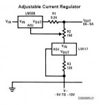
I just remembered of another smart implementation I saw mentioned in a datasheet, the diagram is attached. It could save me a volt or so, and make a 24VDC output suitable...it could even be used to adjust for small current differences between GM70's to attain 20V across the filament. I will at least have to try it out")
Erik
Thanks again! You are right, 24VDC could not be enough when using the LM338. If I remember well most of the 24VDC supplies I have seen have the adjustment possibilities of +/-10%, so I will surely keep that in mind when buying one.
I just remembered of another smart implementation I saw mentioned in a datasheet, the diagram is attached. It could save me a volt or so, and make a 24VDC output suitable...it could even be used to adjust for small current differences between GM70's to attain 20V across the filament. I will at least have to try it out
Erik
Attachments
ErikdeBest said:Hi Kevin
Thanks again! You are right, 24VDC could not be enough when using the LM338. If I remember well most of the 24VDC supplies I have seen have the adjustment possibilities of +/-10%, so I will surely keep that in mind when buying one.
I just remembered of another smart implementation I saw mentioned in a datasheet, the diagram is attached. It could save me a volt or so, and make a 24VDC output suitable...it could even be used to adjust for small current differences between GM70's to attain 20V across the filament. I will at least have to try it out
Erik
Hi Erik,
Needless complicated, you can do the same thing with a single chip and it doesn't address the drop out issue at all.. It just allows you to adjust to 0 current - a feature you actually do not need.. You can accomplish much the same thing by connecting a small pot across the current sensing resistor. (Say 100 ohms or so) Just be sure to place a load across the output otherwise you will get the supply voltage on the input minus the device's internal unloaded voltage drop..
audiodesign said:Can be used a 6c33c-b or 813 socket ?
The holes are too small so you need to drill them up first. Use a drill made for glass or ceramic and lots of cooling.
Just an update on the socket issue. I have a pair of drilled 813 sockets and the contacts deflect on the fat pin on insertion (plate) and I am concerned about the overall lack of clearance between that and the adjoining pins.
I will be running at 1KV and think that the clearance is insufficient for those voltages - along with the sharp edges on the contacts I suspect that corona discharge and arcing are a real possibility.
As expensive as the teflon Yamamoto socket is (and not withstanding my other real objections to them) I am considering them as the clearances are much greater due to the contact design.
I have asked to Jakeband to develop the sockets for 813 and GM70
www.jakeband.it
soon these should be ready and the price will be good
www.jakeband.it
soon these should be ready and the price will be good
I've heard about cold flow with the teflon sockets - you might want to check that out before paying big bucks. If you're using drilled out sockets, you can remove the contacts that aren't used. If they're riveted in like I think they are, it'd be easy to drill out the rivets.
I bought some ceramic sockets from a Chinese vendor on E-pay that have only the needed contacts populated. They weren't all that expensive, either.There are also some Russian gold-plated sockets lurking there. I'm thinking of adding some extra retention for safety's sake (maybe something like a dressier version of a cap clamp), as I don't thing that just four contacts are enough to reliably hold a big tube like the GM70 firmly in place.
I bought some ceramic sockets from a Chinese vendor on E-pay that have only the needed contacts populated. They weren't all that expensive, either.There are also some Russian gold-plated sockets lurking there. I'm thinking of adding some extra retention for safety's sake (maybe something like a dressier version of a cap clamp), as I don't thing that just four contacts are enough to reliably hold a big tube like the GM70 firmly in place.
Mine only have the 4 pins installed - they're modified, however the clearance to the next adjacent pin (grid I think) is insufficient for 1kV operation.
I've used Yamamoto sockets off and on for about 11yrs now, and have not had problems with creepage, the problems I have had all relate to the contacts loosing tension and becoming intermittent. This can be fixed, but on such an expensive socket this IMO should not be necessary. These sockets mostly went into amplifiers purchased by wealthy individuals typically with the mechanical aptitude of a snail.. These sockets have been the source of most if not all of the headaches encountered with these amplifiers.
I've used Yamamoto sockets off and on for about 11yrs now, and have not had problems with creepage, the problems I have had all relate to the contacts loosing tension and becoming intermittent. This can be fixed, but on such an expensive socket this IMO should not be necessary. These sockets mostly went into amplifiers purchased by wealthy individuals typically with the mechanical aptitude of a snail..
These sockets have been the source of most if not all of the headaches encountered with these amplifiers.I have asked to Jakeband to develop the sockets for 813 and GM70
www.jakeband.it
soon these should be ready and the price will be good
What is the time frame on these? I'm at the point where I would like to start building my amplifiers within the next month or so.
I did get a quote for the GM70 sockets made by Yamamoto and needless to say they are quite expensive. Just under 59 € each - will they be much cheaper than this and does Jakeband accept paypal?
I hauled out one of my GM70s to have a look, and it appears to be a sensible design, with the grid and plate being the two pins farthest apart, and the two cathode pins closest together. The Zang Sheng GM70 sockets I have look like they have decent clearance between the grid and plate pins. However, since the mounting plates are made of fairly rough unglazed ceramic, it would also be easy to use some insulating material (mica sheet, for instance) and some JB Weld to put some creepage barriers between the two pins. I may do just that.I plant to use somewhere between 900-100V on the plate, so I could reasonably expect peak plate voltages considerably in excess of that - better to be safe than have to buy another output transformer, or have a grid-to-plate arc take out the rest of the amp.
I betcha there's some Hypertronics-style contacts that could mate to the GM70 pins. One could whip together a neat socket with some ceramic tile and Hypertronics pins.
I betcha there's some Hypertronics-style contacts that could mate to the GM70 pins. One could whip together a neat socket with some ceramic tile and Hypertronics pins.
Be careful using JB weld around HV,In one project I used it in involving magnets,I found that it is quite magnetic,presumably because it contains metal powder. Just a FYI.
Normal epoxy should be fine though.
Too bad, as the base resin for JB Weld is some tough stuff - I'll have to find something similarly durable without the metal filler.
The concern I have with my sockets is the sharp edges on the contact springs and because of the design of the contacts there is not nearly as much clearance as you would expect given the pin spacings.
I may try epoxied barriers on either side of the plate pin to increase the creepage distances and/or I may grind off the sharp edges on the contacts to gain some additional clearance.
I purchased a new Rega oem RB300 tone arm for another project so I will have to wait a few weeks on those sockets in any event..
- Status
- This old topic is closed. If you want to reopen this topic, contact a moderator using the "Report Post" button.
- Home
- Amplifiers
- Tubes / Valves
- GM70 sockets?