Anatolyi: "I am going to try a double-drive such a way: 1..2..3..4..5.."
George: "OK, why not one typical P-P driver with each output feeding a pair of mosfet drivers (4 total). Each mosfet has independent gain and DC bias adjustments."
Ken: "driving G1 from the lower 533R"
I'm smelling success now.
"It's impressive that anyone still living knows Lewis Carroll..."
I thought it was Rudyard Kipling who spoke about "taking the road less traveled..." I guess they didn't have GPS back then.
Don
sorta OT: Say Darius, I recall you were looking for a tube with a Mu of 1 a while back. I just ran across a data sheet that mentions just that (bottom 1st page):
http://www.mif.pg.gda.pl/homepages/frank/sheets/093/6/6AH6.pdf
But probably rather high rp with this tube. Could try g3 drive with some low rp pentode instead.
Don
http://www.mif.pg.gda.pl/homepages/frank/sheets/093/6/6AH6.pdf
But probably rather high rp with this tube. Could try g3 drive with some low rp pentode instead.
Don
Re: @ #20
Hi Darius,
I did so.
No, it is not, and you would know and agree if you would have done some grid current measurements for such conditions yourself.
Regards,
Tom Schlangen
Hi Darius,
note the 22K resistor in series to g1.
I did so.
It is false to say they are tied together.
No, it is not, and you would know and agree if you would have done some grid current measurements for such conditions yourself.
Regards,
Tom Schlangen
kenpeter said:
If you find yourself needing to adjust the overall amount of UL,
resistive plate to plate (output plates back to the concertinas)
feedback might be handy.
Great idea, thanks!

Maybe you mean the schematic as attached below.
That is the one. I played with this several years ago and wasn't impressed. The effective Mu of the "triode" wired tube is quite high. It likes to oscillate! You need to tweak the 22K resistor value for best linearity. Too low and your driver gets mad, too high and the output stage distorts. You need a resistor on the screen too. This circuit was conceived before mosfets were popular. We can do better today.
I'm smelling success now.
You might be smelling success, but I am smelling the fine aroma of burnt parts. Lets see...... this one is Allen Bradley, 1969......
Which component do you most expect to burn up, and why?
Or are you referring only to the older class B amp?
As for oscillations: I always thought the cause was unterminated
resonant stubs. Low impedance on one end, high impedance on
the other, and a quarter length "whip antenna" of some resonant
frequency. Then you abuse the high voltage/high impedance/low
current end of that resonant antenna stub as one of the control
elements of a tube or FET, and let it pick up stray garbage from
the amplified output.
Or high impedance both ends, and resonant on the half wave...
Which component do you most expect to burn up, and why?
It was a poor attempt at humor. But I do have a history of toasting parts. Sometimes you just know something is going to fry and it works great. Other times you have this great idea, and the fire gods just dance all over it.
As for oscillations: I always thought the cause was unterminated resonant stubs.
Sometimes it is just stray capacitance resonating with leakage (and other unwanted) inductances being excited by the abrupt spike created when an output tube is driven to cutoff. Some circuits just want to oscillate. Some circuits may exhibit some oscillitory instability without the user being aware of it. I tend to "sniff" my tube circuits with an RF spectrum analyzer while driving them to clipping. My full time job is transmitter design, so it is just a habit.
@#24 807 off topic here, grids not tied together.
Thanks to tubelab.com")
Kind regards,
Darius
Originally posted #24by Tubes4e4
...
No, it is not, and you would know and agree if you would have done some grid current measurements for such conditions yourself. ...
Originally posted #26by tubelab.com
That is the one. ... You need to tweak the 22K resistor value for best linearity. Too low and your driver gets mad, too high and the output stage distorts. ...
Thanks to tubelab.com
Kind regards,
Darius
Wavebourn said:I am going to try a double-drive such a way:
1. Differential phase splitter,
2. 2 asymmetrical Concertinas (higher value of resistors in anodes) coupled to each anode of a diff stage directly;
3. Source followers from their anodes to screen grids of output pentodes,
4. Capacitive coupled cathodes of Concertinas to control grids of output pentodes.
The result should be kind of opposite to UL mode.
Ok, let's draw the schemo in imagination.
First tube: a pentode 6J53P, 120V on screen grid, 27K from anode to 250V, cathode resistor sets 90V on anode, current is 10 mA (it's happy).
Second tube: 6N1P, 56K in both anodes to 250V, 175V on anodes, 3 mA ccs in tail,
One grid of diffstage connected to anode of 6J53P through 100K grid current limiter shunted by 200 picofarad, second grid connected to the same anode through 2 megaUhm, and grounded through 0.47 microFarad,
Now, concertinas.
IRF740, directly connected gates to anodes of a differential phase splitter, sources connected directly to screen grids of GU-50 tubes.
What current draw screen grids? We have 172V there idle.
Depending on the current and swing needed for control grids now we may choose resistors from drains to +400V B+ supply...
0.33 microfarad capacitors go from drains to first grids of Gu50.
As the result, we have almost directly coupled thingy that drives both grids of GU-50 so can get a good damping factor on low end.
You have made the mistake of posting an actual professional
schematic on more than one occasion. Good ones at that.
What now, is your mouse broken? Or maybe you gone full-
Prof Hawking on us, and would have to draw with your chin?
Sorry to hear about that... Get well soon.
Pics please.
schematic on more than one occasion. Good ones at that.
What now, is your mouse broken? Or maybe you gone full-
Prof Hawking on us, and would have to draw with your chin?
Sorry to hear about that... Get well soon.
Pics please.
hey-Hey!!!,
The 172V idle is the deal killer. At that g2, there will have to be negative at g1, and it sure looks to me like that one should be tied to either g2 or better still the cathode. We'd be running some serious idle current I think.
Also, what is the attraction to run the input stage's plate lower than its g2? Adjust the load, and then the g2 so it comes out lower than the anode I think. The Citation II did this in spades, and I suspect that it would work better at a more likeable OP.
cheers,
Douglas
"0.33 microfarad capacitors go from drains to first grids of Gu50."
I take it that the IRF740's are acting as both source followers for the screen grids and as concertinas to derive g1 drive off their drain resistors. One problem I see is that the varying screen current (ie, non-linear varying screen current) will affect the signal gain to the g1s.
I would suggest using a source follower off the diffl. splitter plates for the g2 drives and connect their drains to the tube plates. That way the screen current gets returned to the output, making for very linear outputs. The g1 drives --could-- come directly (well, cap coupled and resistive divided) off the differential splitter plates if they are low enough Z to drive both g1 and the Mosfet gate.
Or just go with George's approach and resistively divide down the g2 voltage (from the Mosfet source) to get the g1 drive (probably don't need another Mosfet follower for g1 since the divider will be low Z there).
You will need some provision to adjust the DC idle condition on the g2s (at the MOsfet gates) for non flaming system operation.
Don
for non flaming system operation.
I thought I smelled smoke.
Or just go with George's approach and resistively divide down the g2 voltage (from the Mosfet source) to get the g1 drive (probably don't need another Mosfet follower for g1 since the divider will be low Z there).
When I don't know what I am doing, I like to have as many knobs to turn as possible. The two mosfet approach allows the DC and AC voltage to be adjusted individually for each grid. This could be done with only R's and C's for G1 on many tubes where grid current is low, but why limit yourself to wimpy tubes. Who knows I may find myself wiring an 813 into the circuit
I think the mosfet concertinas are a good idea. In his application,
Plate to Plate (or Drain) feedback might be used for UL. Triode
coupling down to the cathodes and then to the opposing grids,
would be an unintended positive feedback loop. Mosfets won't
couple through in that manner, so no such problem can arise.
I still want him to draw it.
Plate to Plate (or Drain) feedback might be used for UL. Triode
coupling down to the cathodes and then to the opposing grids,
would be an unintended positive feedback loop. Mosfets won't
couple through in that manner, so no such problem can arise.
I still want him to draw it.
Anatolyi:
"IRF740, directly connected gates to anodes of a differential phase splitter, sources connected directly to screen grids of GU-50 tubes."
"0.33 microfarad capacitors go from drains to first grids of Gu50."
Ken:
"Plate to Plate (or Drain) feedback might be used for UL. "
My take on the first quote is that the Mosfet concertina sources are driving the g2s and the Mosfet drain resistors are driving the g1s. I think you are picturing the two drives swapped. (A diagram would be helpfull here of course)
Could still use plate to gate neg. feedback (like UL) like you say, but that would affect both g2 and g1 drives in this setup.
Don
Why would he put the higher value resistor at the anode if it
was his intent to drive G1 from there? I don't think he meant
that it should be connected that way, but without some sort
of vague chicken scratchings on the back of a pizza coupon in
broken crayon, we can never be sure.
Translation: Gonna look pretty silly if we have to get Don to
draw it for you.
was his intent to drive G1 from there? I don't think he meant
that it should be connected that way, but without some sort
of vague chicken scratchings on the back of a pizza coupon in
broken crayon, we can never be sure.
Translation: Gonna look pretty silly if we have to get Don to
draw it for you.
Sorry Gentlemen;
last night I suffered from a tooth pain, so smocked in garage reading the forum. I have a mouse there on server, but no drawing software.
Yes, control grids need a negative bias.
Yes, they will be driven non-linearly depending on screen grid currents, but my tooth felt like this weird idea may lead to good end results.
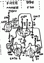
"vague chicken scratchings on the back of a pizza coupon"
You mean like this?
I couldn't find a crayon handy though.
Don
OOPs, I just noticed that the GU50 g1 drive signals need to be crossed over between tubes due to the Mosfet's inversion at its drain. Hmmm, so the non-linear screen current only effects the "OFF" tube's g1 drive. Hmmmm, but then the Mosfet driving the "ON" tube's g1 has no current thru it's drain resistor. I think some fixup is called for here.
Attachments
- Status
- This old topic is closed. If you want to reopen this topic, contact a moderator using the "Report Post" button.
- Home
- Amplifiers
- Tubes / Valves
- LS50/GU50 Both Grid Drive