All this talk of mains toroids and DC compensation gave me an idea
for an interstage coupling circuit.
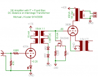
It's basically an inverting interstage transformer with CCS bias
on the secondary to act as both DC cancellation of the driver
current and current supply to a shunt bias regulator for the
output tube.
This could be great for A2 drive also, since the driver will be at
it's low-Rp, high current extreme when driving the grid positve.
Just the thing to motivate building a SE project.
Cheers,
Michael
for an interstage coupling circuit.
It's basically an inverting interstage transformer with CCS bias
on the secondary to act as both DC cancellation of the driver
current and current supply to a shunt bias regulator for the
output tube.
This could be great for A2 drive also, since the driver will be at
it's low-Rp, high current extreme when driving the grid positve.
Just the thing to motivate building a SE project.
Cheers,
Michael
Attachments
Don't go getting all distracted. I want to see how this one comes out: http://www.diyaudio.com/forums/showthread.php?s=&threadid=128950
Specially this version: http://www.diyaudio.com/forums/showthread.php?postid=1599359#post1599359
Sheldon
Specially this version: http://www.diyaudio.com/forums/showthread.php?postid=1599359#post1599359
Sheldon
Hi Michael
Interesting idea, I saved the thread for whenever I have time to try it out, but I already have one question about the interstage transformer. You define it as a 1:1 at 15VA. Do you know where one can get such a trafo? For small power units I only found toroids with the secondaries with much lower voltages (like 2x115V on primary and 2x15V on secondary).
Many thanks, Erik
 ! Have you measured the inductance?
 !
!This is true. I realized as I was writing it up that it might be best to
use a purpose-built IT ungapped or with a small gap for ~5mA to
handle some drift. I do have some of the Hammond isolation toriods
(182D110 and 1182E117) but they are not cheap to buy at $40US)
I should get around to measuring the inductance but I will likely
make in-circuit measurements on my little spud amp with different
transformers clipped in.
Sheldon - I'm currently building an amp based on the parafeed
circuit, waiting for a pair of 6S45pi to arrive from Russia to try
also. Maybe I can abuse the 5842s some more in the meantime.
Stay tuned on the push-pull circuit. I'm thinking about a self-bias
version that might have good DC stability. I don't want to add
any parts, though!
Michael
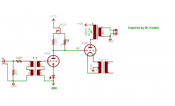
Rev, you might want to tap that FET at the source (for Mu follower
with lowest drive impedance). Or if you are going for MJK inspired,
design, halfway up the current sense resistor. At the "Anti-triode"
balance.
Its a good thing Michael hasn't discovered the Hall Effect yet.
with lowest drive impedance). Or if you are going for MJK inspired,
design, halfway up the current sense resistor. At the "Anti-triode"
balance.
Its a good thing Michael hasn't discovered the Hall Effect yet.
Lars:
I have a lot of sketches like your schematic, but it comes
down to ? DC stability of using a CCS-loaded driver tube
to provide fixed bias. I have not tried building it yet...
Replace the CCS with a choke and use combination bias
for better DC stability and that's pretty much the amp
design I've been building. Also the choke eliminates the
3rd power supply.
I don't expect a mains toroid to perform well at line
levels though, and I've been spending up to $150
each for a good line input transformer (repeat coil)
UTC A-20s are good at about $100/pair on ebay.
Again I have not tried the toroid as a line repeat coil
but maybe a 5VA unit with a tiny core...
I would like to figure out a build like your picture some
day with CCS DC coupling, just haven't come up with
the one yet.
Ken:
Can I do a Hall-effect servo with 3 parts or less? Hmm...
Michael
Interwinding capacitance is the killer in this application. I had to push 30mA of current through my driver tube to get a decent response. Even then its somewhat rolled off on the top end.
If you can design it with a 2:1 voltage step down I would expect it to perform much better. I have used one as an input transformer with a step down of 9:1 and it works great.
Shoog
If you can design it with a 2:1 voltage step down I would expect it to perform much better. I have used one as an input transformer with a step down of 9:1 and it works great.
Shoog
- Status
- This old topic is closed. If you want to reopen this topic, contact a moderator using the "Report Post" button.
- Home
- Amplifiers
- Tubes / Valves
- Mains toroid as IT with DC balance?