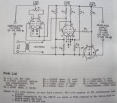
Has anyone ever built the 250vdc voltage regulator in the back of later RCA tube manuals? I tried breadboarding this but it doesn't work well at all. Not much regulation and R5 dissipates a lot of power when the pot is turned down (output voltage goes up). Anything look wrong with the schematic?
Attachments
I don't like it. Too complex, and this is one of those situations where KISS applies. Here are a couple of hollow state active regulators I designed and built. This one is a rather conventional design adapted from a solid state regulator. The 6CB6 small signal pentode is a high gain device with an unusually high Vhk rating that makes it convenient for error amp duty. It works just fine, and holds its output voltage to 0.8V for a rail change of 40V. The project it's in has been in operation since December, 2005 and the output voltage hasn't moved at all in that time.
Attachments
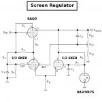
Here's a somewhat different version. For this, the 6KE8 triode/pentode type operates as a cathode coupled error amp. The voltage gain section is the pentode, another high gain type. The triode section couples in the reference voltage. This allows the inclusion of an RC LPF to reduce noise and to take a load off the voltage reference tube. This would correspond to the noninverting input of an op-amp. It's a bit more complex, but it operates just as good as the simpler version. This one also hasn't shown any signs of drift over time.
Attachments
Thanks for the schematics Miles. It looks like my ignorance of how the design actually works is showing. Varying the load resistor does indeed keep the voltage steady, however varying the input voltage causes the output to change. R5 is underrated on the parts list. It dissipates 2w with 250v out.
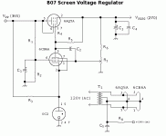
This is for a small PP pentode amp. I found a nice design from Sound Practices using a 6BM8 to regulate the screens. This larger regulator is for the main B+. Using a regulator seems like a more elegant way to drop some excess B+ voltage.
This is for a small PP pentode amp. I found a nice design from Sound Practices using a 6BM8 to regulate the screens. This larger regulator is for the main B+. Using a regulator seems like a more elegant way to drop some excess B+ voltage.
I wouldn't say it's complex, it's a classic regulator circuit that dates back over 50 years and can be found, along with others (including screen regulators), in ARRL manuals from the 1950's. I built this circuit over 30 years ago (my Dad built it over 50 years ago) and it performs well. Also note that it has a specific input voltage from 325 (full load) to 375 volts (no load) with a specified output of 250 volts. Have you exceeded the input voltage? What is your target output voltage?
Note that you can re-bias it, but pay particular attention on the 5651 tube. This is NOT a shunt regulator but a voltage reference tube and has a narrow operating range from 1.5ma to 3.5 ma (max) and should be targeted around 2.5ma average current. If you have good tubes and good layout it should work fine.
Regards, KM
Geek said:I've used a small-tube variant of Miles' screen regulator and it's pretty much the defacto for regulated supplies now. It's a good one
Cheers!
what are some typical component values?
TIA,
Here's the schematic for the one I did:
http://geek.scorpiorising.ca/GeeK_ZonE/index.php?topic=3665.0
Maybe Miles could provide info on the ones he used?
Cheers!
http://geek.scorpiorising.ca/GeeK_ZonE/index.php?topic=3665.0
Maybe Miles could provide info on the ones he used?
Cheers!
For the regulator with the 6KE8 error amp:
C1: 1u0
C2: 0u033
C3: 0u1
R1: 470R
R2: 4K7
R3: 60K / 2W
R4: 50K / 1W
R5: 200K
R6: 6K8 / 5W
R7: 1M
R9: 6K8 / 2W
R10: 139K
R11: 25K (Multiturn cermet)
R12: 136K
The design isn't quite so easy as the solid state version where you always know that Vbe= 0.6V all the time. So you use loadlines as you would for any other aspect of hollow state design to set Q-Points and determine component values.
I don't like it. Too complex, and this is one of those situations where KISS applies. Here are a couple of hollow state active regulators I designed and built. This one is a rather conventional design adapted from a solid state regulator. The 6CB6 small signal pentode is a high gain device with an unusually high Vhk rating that makes it convenient for error amp duty. It works just fine, and holds its output voltage to 0.8V for a rail change of 40V. The project it's in has been in operation since December, 2005 and the output voltage hasn't moved at all in that time.
Miles,
Can either of these be tweaked to provide a 600 volt regulated output? I like the topology of the one with the 6KE8 error amp.
TYVM,
-- josé k.
I currently use couple of 120V Zeners in series and one IRF730 as a voltage follower. More than enough for screens of 4 tubes GU-50 and couple of preamps/phase splitters.
me too....you can even delay the b+ for the screens using proper combination of RC....

- Status
- This old topic is closed. If you want to reopen this topic, contact a moderator using the "Report Post" button.
- Home
- Amplifiers
- Tubes / Valves
- RCA voltage regulator