Hello,
I'm thinking how well would a toroidal mains transformer work as an output transformer. You may need to modify the secondary winding to get the correct transform ratio but there should be not much problems in that because in toroid the secondary is on top and extra windings easy to remove. (I've modified toroid earlier also but for different purpose)
So the starting point could be for example 230V/12V 120VA toroid which are easy to find and quite cheap too.
How will the distortion level be in these kind of toroids? The power rating should be enough for <10W output, right?
How about bandwidth? I would guess that because the big and heavy toroid is initially designed for 50Hz, it could support low frequencies quite ok? I don't know what will happen at 20kHz though?
Which one would be better actually, a toroid or 'square' iron core mains tranformer for this purpose?
Please share your experience")
- Elias
I'm thinking how well would a toroidal mains transformer work as an output transformer. You may need to modify the secondary winding to get the correct transform ratio but there should be not much problems in that because in toroid the secondary is on top and extra windings easy to remove. (I've modified toroid earlier also but for different purpose)
So the starting point could be for example 230V/12V 120VA toroid which are easy to find and quite cheap too.
How will the distortion level be in these kind of toroids? The power rating should be enough for <10W output, right?
How about bandwidth? I would guess that because the big and heavy toroid is initially designed for 50Hz, it could support low frequencies quite ok? I don't know what will happen at 20kHz though?
Which one would be better actually, a toroid or 'square' iron core mains tranformer for this purpose?
Please share your experience
- Elias
Hi Elias
Search some old threads, there is already a lot of discussion on toroidals as output transformers.
More specific on your question regarding the 230/12 transformer. This is about 20:1, or an impedance relation of 400:1. A speaker of 8 ohms on the secondary giver 3k2 on the primary, which is a nice value for a lot of valves out there. But a single primary implicates that it can only be used in either SE or parafeed. The application in SE will probably be disastrous: the DC current will saturate the core...the application in parafeed may provide better results. A better option is a 110V+ 110V primary: connect both in series, apply the B+ to the CT and the extremes go to the plate of a PP stage The low voltage secondary goes to the speaker). Still better (technically speaking) would be tubelab's suggestion: get yourself an isolation transformer (220V to 220V, or 220V to 110V+110V, etc), connect the windings in serie for a CT winding (take care that each halve has the same amount of turns) and use this as a primary. The secondary you have to wind yourself, but as you said, that is relatively easy to do by hand. The advantage is that you have more inductance on the primary!
Erik
Hello,
simple SE amplifier I have on my mind. Core saturation of ferrite core could be an issue. Thanks for pointing that out Erik. However I have no measured data to show how much DC a toroid can take before saturation.
The idea in the Jaime's link can have merit. At least it avoids DC.
Image copied from the link:

Well, still wondering about the sound quality of toroidal transformer..
How about core hysteresis, which can be high in ferrite cores? That cannot sound very good?
- Elias
simple SE amplifier I have on my mind. Core saturation of ferrite core could be an issue. Thanks for pointing that out Erik. However I have no measured data to show how much DC a toroid can take before saturation.
The idea in the Jaime's link can have merit. At least it avoids DC.
Image copied from the link:
Well, still wondering about the sound quality of toroidal transformer..
How about core hysteresis, which can be high in ferrite cores? That cannot sound very good?
- Elias
Hi Elias
Bad tongues say a toroidal can take very little DC (with the exception of the SE versions developed by amplimo/plitron, but I do not know which technique they used...) before saturating, and this is due to their perfectness (valve amplifiers goes deeper in the theme).
People from this list used toroidals as output transformers (again, in PP or parafeed) and most (or all) were quite impressed by the positive results: good bandwith, blabla. As for the sound quality, that is subjective: some people would not even consider toroidals as they do not look like 'traditional' trafos. I myself also used a toroidal once, and it sounded fine...but then, it was one of my first projects and I did not compare to a good quality EI trafo.
As said before, do a search on toroidal. Pay special attention to posts by Shoog, as he has done several designs using toroidals, from input to IT's to output.
Here is a recent thread showing an amplifier were a toroidal could be used as well
http://www.diyaudio.com/forums/showthread.php?s=&threadid=128950
Erik
> Here is a recent thread showing an amplifier were a toroidal could be used as well
> http://www.diyaudio.com/forums/showthread.php?s=&threadid=128950
I'm using a 25VA Amveco mains toroid in a test amp. I used
that one because it was the largest one I had and I thought the
primary inductance would be better than the 15VA ones.
I'm using it in a parafeed circuit very similar to Diego's, using a
MOSFET as an anode load with active complementary current drive
First description I know of is at:
http://www.diyaudio.com/forums/showthread.php?postid=638005#post638005
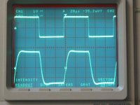
Anyway, the transformer's performance as a parafeed audio output
is excellent. It has no finite inductance effect down to the Fc of 8Hz
set by my parafeed cap, and the upper Fc is about 40 KHz (-3db).
Attached is a scope photo of a 10KHz square wave.
These results are using the primary at 2K ohms impedance.
I don't know what happens if you go up to higher impedance but
I guess it may affect the HF performance somewhat.
The sound is fine. I haven't done a direct comparison but this amp
sounds like a good SET. It's nice and detailed, seems to have great
frequency range, and I don't think the transformer is negatively
affecting the sound, i.e. it's doing what a transformer should do.
I would not hesitate to use these in an inexpensive project to
check it out for yourself. If they saturate at 25VA at 60 Hz, they
should be good for a few watts down to 20 or 30 Hz. I think there
is a lot more info on this on other threads here as cited.
Cheers,
Michael
> http://www.diyaudio.com/forums/showthread.php?s=&threadid=128950
I'm using a 25VA Amveco mains toroid in a test amp. I used
that one because it was the largest one I had and I thought the
primary inductance would be better than the 15VA ones.
I'm using it in a parafeed circuit very similar to Diego's, using a
MOSFET as an anode load with active complementary current drive
First description I know of is at:
http://www.diyaudio.com/forums/showthread.php?postid=638005#post638005
Anyway, the transformer's performance as a parafeed audio output
is excellent. It has no finite inductance effect down to the Fc of 8Hz
set by my parafeed cap, and the upper Fc is about 40 KHz (-3db).
Attached is a scope photo of a 10KHz square wave.
These results are using the primary at 2K ohms impedance.
I don't know what happens if you go up to higher impedance but
I guess it may affect the HF performance somewhat.
The sound is fine. I haven't done a direct comparison but this amp
sounds like a good SET. It's nice and detailed, seems to have great
frequency range, and I don't think the transformer is negatively
affecting the sound, i.e. it's doing what a transformer should do.
I would not hesitate to use these in an inexpensive project to
check it out for yourself. If they saturate at 25VA at 60 Hz, they
should be good for a few watts down to 20 or 30 Hz. I think there
is a lot more info on this on other threads here as cited.
Cheers,
Michael
Attachments
Hello,
It's good to hear Michael that you've had good results with toroids. Seems promising for me too.
Actually at this point I would try to find some way to avoid semiconductors in the signal path. I've done silicon amps before and now I'd like to try something different. I'm thinking building a simple SE without exotic and expensive components, a sort of starting point for me.
I know the active loading will work, but at first I'll try to keep it passive.
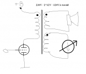
I came accross this old idea using DC bias curent at the secondary to compensate magnetic field from primary DC current. Looks good and simple on paper. Can make it adjustable if you like to try different levels of magnetisation of the core.
Anyone tried it in practise?
It's good to hear Michael that you've had good results with toroids. Seems promising for me too.
Actually at this point I would try to find some way to avoid semiconductors in the signal path. I've done silicon amps before and now I'd like to try something different. I'm thinking building a simple SE without exotic and expensive components, a sort of starting point for me.
I know the active loading will work, but at first I'll try to keep it passive.
I came accross this old idea using DC bias curent at the secondary to compensate magnetic field from primary DC current. Looks good and simple on paper. Can make it adjustable if you like to try different levels of magnetisation of the core.
Anyone tried it in practise?
Attachments
I finished a PP KT88 using Talema toroidal tranformer as OPT. 120VA, 2X 115V primary, 2X 12V secondary (paralleled). I unwound some of the secondary so that it will give me 10V, with 8 ohm speaker load, primary Z is 4.2K.
I also used an autoformer (center tapped choke) to do phase inversion (just like how Jack Elliano executed a couple of PP amps on his site).
At first I was getting very attenuated bass and I thought it was the toroidal tranformer, but later found out that it was the combination of the capacitor and the autoformer phase inverter, forming a low frequency filter. When I increase the size of the coupling capacitor to 3.3uf, wow!
Am using 400VDC B+, paralleled 6n1p as driver (22K plate load, 500R cathode resistor bypassed with 100uf) , the output tubes triode strapped and cathode biased using a common 250R resistor and bypasedd using 220uf cap.
I've used 230:9+9 30VA and 50VA units SE with good results . One secondary is used for output to the speaker , the other is used to offset the DC in the secondary , for this a high impedence DC source is used . I fed the filaments of a 6B4G (6.3V/1A) with DC using a 280mH isolation choke and placed one of the secondaries in series with this . The transformer is 25:1 , so 1A of filament current offsets approx 40mA of anode current . Requires a variable fixed bias supply for optimum results but worked ok with a cathode bias network also . Takes a bit of tweaking to get right , there is a window of approx 2mA either side of the 40mA figure before audiable saturation occurs .
cheers
316a
cheers
316a
Hello,
Interesting. So many good experience with toroids. Sounds very promising for me.
326a:
2mA tolerance comes to +/-5% which can be hard to maintain during long periods if considering tube ageing? Or can we assume tube bias current will allways stay within +/-5%?
Maybe can use a correction circuit for setting the toroid secondary DC bias. The gain in the DC feedforward path is the same as toroid winding ratio. This should maintain correct compensation current in the secondary regardless of tube bias current changes. Can even tune the tube bias if you wish to try how it affects the sound and at the same time keep the toroid in it's optimum performance. I'm sure this idea is not new even I don't recall seeing it before.
- Elias
Attachments
Hi Elias
You are really good in reinventing the wheel! There is a quite recent thread were a member presents an amplifier with exactly this topology, a tracking CCS in one of the windings.
http://www.diyaudio.com/forums/showthread.php?s=&threadid=118725&highlight=
Yesterday I looked into my toroidal stock and found some 230V to 24V + 24V units. I thought about using one for output transformer for a 6C33C operated at about 250mA. Soon I concluded that I would need to inject about 2,5A in the 24V winding. I measured the DC resistance of the 24V winding which should be about 0.3R...injecting 2,5A would develop 1V, which is not much, but then, how to accomplish a fine control over the 2,5A? I thought about using an LM338 set as CCS for the job, but there would be at least a 4V drop over it and the current setting resistor...that is 10W dissipation. Hmmm...better would be to use a trafo with 2 110V windings, one for the output tube and the other for DC cancellation...but the 230V winding is much more appealing, as it will present larger inductance.
Maybe a toroidal with dual 18V secondaries. This one would need about 3.2A in the secondary to cancel 250mA in the primary. One could then feed the 6C33C with 12VDC/3.3A, put one of the 18V secondary in line with the cathode and set the 6C33C bias for best cancellation.
just some thoughts...
Erik
[2mA tolerance comes to +/-5% which can be hard to maintain during long periods if considering tube ageing? Or can we assume tube bias current will allways stay within +/-5%?
Maybe can use a correction circuit for setting the toroid secondary DC bias. The gain in the DC feedforward path is the same as toroid winding ratio. This should maintain correct compensation current in the secondary regardless of tube bias current changes. Can even tune the tube bias if you wish to try how it affects the sound and at the same time keep the toroid in it's optimum performance. I'm sure this idea is not new even I don't recall seeing it before.
The 2mA tolerance either side of 40mA seems to have no discernable effect , after that it takes much more offset for any noticeable distortion to creep in . Best to keep it simple rather than add feedforward or whatever circuitry ! Much better off hooking up a sig gen and DVM every now and again and use variable grid bias to adjust . It's a tweaky circuit , bypassed CCS in the cathode circuit can help but then again the DC filament supply needs to be regulated too . Never tried this as I used a choke input filament supply .
At the end of the day there is a price to pay for using a cheap transformer , as the offset choke and DC filament supply will increase the cost . It's a fun experiment if you have the parts but I'd recommend a pair of Trancendar 3K SE transformers instead . For the price and performance of these units there's no point messing around with chokes and mains transformers !
cheers
316a
Hello,
Erik:
Thanks for the compliment
No that is a one long thread! I need to take some time to go it through.
I would like to have a toroid with for example 230V / 12V + 110V windings. Could reduce the compensation current quite a bit.
316a:
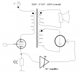
I see no problem putting a feedforward DC feed. Basically all you need for it is one opamp and one power transistor for current generator + some small signal stuff. The price for these parts almost nothing.
Why do you need the choke for? If you put one secondary winding in series with filaments, and drive it with constant current, there is no need for the choke. By definition constant current source will keep the filament in constant potential also. There is no way the signal can be fed back to filaments.
Well, buying a ready made output transformer kills the DIY in it
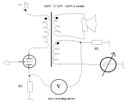
For the passive DC current tracking, can use simple metering circuit. The ratio of R1 and R2 is the same as toroid winding ratio.
I think I need to put the meter in the front panel of the amp, because otherwise it makes me worried if the bias is correct and it prevents me from enjoying the music
- Elias
Erik:
Thanks for the compliment
No that is a one long thread! I need to take some time to go it through.
I would like to have a toroid with for example 230V / 12V + 110V windings. Could reduce the compensation current quite a bit.
316a:
I see no problem putting a feedforward DC feed. Basically all you need for it is one opamp and one power transistor for current generator + some small signal stuff. The price for these parts almost nothing.
Why do you need the choke for? If you put one secondary winding in series with filaments, and drive it with constant current, there is no need for the choke. By definition constant current source will keep the filament in constant potential also. There is no way the signal can be fed back to filaments.
Well, buying a ready made output transformer kills the DIY in it
For the passive DC current tracking, can use simple metering circuit. The ratio of R1 and R2 is the same as toroid winding ratio.
I think I need to put the meter in the front panel of the amp, because otherwise it makes me worried if the bias is correct and it prevents me from enjoying the music
- Elias
Attachments
Elias said:316a:
I see no problem putting a feedforward DC feed. Basically all you need for it is one opamp and one power transistor for current generator + some small signal stuff. The price for these parts almost nothing.
Why do you need the choke for? If you put one secondary winding in series with filaments, and drive it with constant current, there is no need for the choke. By definition constant current source will keep the filament in constant potential also. There is no way the signal can be fed back to filaments.
Well, buying a ready made output transformer kills the DIY in it
For the passive DC current tracking, can use simple metering circuit. The ratio of R1 and R2 is the same as toroid winding ratio.
I think I need to put the meter in the front panel of the amp, because otherwise it makes me worried if the bias is correct and it prevents me from enjoying the music
- Elias
I think you're looking far too deeply into this , maybe perhaps you should build one of these amps and report back ? In the case of a 6B4G , a one amp CCS will not only get hot running with enough compliance but also may have stability problems . You cannot use a centre reading meter with a directly heated valve unless I'm mistaken . I do not see the point in heating an indirectly heated power valve with DC as in your diagram , not only does it add complexity but also cost , which negates the whole point of using a mains transformer in the first place !
cheers
316a
I have messed about with toroidals as outputs a lot. I tried choke loaded SE outputs and Valve CCS loaded outputs. Choke is the better way to go because you lose less voltage. However I think the whole idea of SE toroidals is a big mistake and wouldn't recommend it at all. Having said that, DC compensation would seem to be the way to go. If I did that I would put a CCSink in the cathode to make it rock solid stable over time. Basically choke loads are expensive and introduce all of the nasties which toroidals avoid - so no advantage and no cost saving.
I have three amps using toroidals in PP amps and this is where they shine the most. Response down to 10Hz and up to 60kHz. DC balance is essential and can be achieved with CCsinks in the cathodes, or with "Garter Bias". I like to get my CCS to within 1mA, bass suffers badly after that. LM317's make reasonable candidates for CCS. One thing to watch is because of their extreme bandwidth they do tend to ring and may need dummy loads. I have found that they consistently perform better with the primary winding in one direction against the other. This is a interwinding capacitance issue which both kills the bottom end and produces a rising response centered around 50khz. Reverse the windings and this problem goes away.
Used as phase splitters they benefit from a bit of a step down.
Shoog
I thought DC balance would work on the toroid just fine,
as long as there are 2 complementary devices to cancel the
average current, i.e. push-pull. In SE I have only used parafeed
with a capacitor.
The circuit at
http://www.diyaudio.com/forums/showthread.php?s=&threadid=118725&highlight=
uses a MOSFET opposite a tube with a PP OPT. The MOSFET is
controlled to both balance DC current and actively drive signal
current inverse to the tube's signal current. I also experimented
with just DC cancellation.
I have noticed some interesting transformer saturation effects
based on different DC balance schemes.
Basically, what happens is that if you balance the DC at idle,
then at full signal there is a DC shift due to the load-line
asymmetry. The increasing current swing is greater than the
decreasing current swing, and when a large signal is applied
the average current increases. If the DC balancer is fixed and
adjusted at idle, there will be a DC offset at large signal.
The PP transformer I used tolerated a few MA of unbalanced
DC current, so I didn't have a lot of saturation problems to
deal with. Your experiences with the toroid will be interesting.
Michael
PS The "zero crossing meter" if damped properly would display
this DC shift with signal
That depends mainly on the primary inductance. If you want any bass at all you should be looking for the highest primary inductance you can get.Elias said:Hello,
How about bandwidth? I would guess that because the big and heavy toroid is initially designed for 50Hz, it could support low frequencies quite ok? I don't know what will happen at 20kHz though?
Cheap toroids may have less than 1 Henry, which is useless. You might get lucky and find one with around 10 Henrys, which would be "useable" for lo-fi applications using pentodes (such as a guitar amp or radio), but if you want to get anything that remotely looks like hifi you''ll have to use it with a low impedance valve, like a nice beefy triode. Couple of triode-strapped ECL86s maybe.
My personal experience of using toroidals is with
- 6080's running at 100V 100ma, very low output impedance.
- ECL82 with plate to plate feedback which reduces output impedance down to CF levels.
- 807 with plate to plate feedback as well.
So all of my applications have had very low output impedance finals which makes my experience less than generally applicable.
However I believe Steve Bench made his Matrix amps with toroidals as outputs and he measured very high inductances and very good results. I think experience is stacking up to show that they work well and work well down to very low frequencies - better than many SE transformers.
Shoog
- 6080's running at 100V 100ma, very low output impedance.
- ECL82 with plate to plate feedback which reduces output impedance down to CF levels.
- 807 with plate to plate feedback as well.
So all of my applications have had very low output impedance finals which makes my experience less than generally applicable.
That depends mainly on the primary inductance. If you want any bass at all you should be looking for the highest primary inductance you can get.
Cheap toroids may have less than 1 Henry, which is useless. You might get lucky and find one with around 10 Henrys, which would be "useable" for lo-fi applications using pentodes (such as a guitar amp or radio), but if you want to get anything that remotely looks like hifi you''ll have to use it with a low impedance valve, like a nice beefy triode. Couple of triode-strapped ECL86s maybe.
However I believe Steve Bench made his Matrix amps with toroidals as outputs and he measured very high inductances and very good results. I think experience is stacking up to show that they work well and work well down to very low frequencies - better than many SE transformers.
Shoog
Hello,
Ok, I did some measurements. I had 115V+115V / 43V / 105VA toroid. One primary I fed with signal generator with 100ohm impedance, the other primary I fed with 0...100mA DC current with 470ohm series resistor and the secondary I loaded with 8ohm resistor. I monitored sinusoidal voltage over the load resistor with oscilloscope. The signal power transferred to the load was about 1W.
The result:
I observe no change in waveform when I change the DC current. No change at all! Waveform at the load remain exactly the same with or without DC current in primary.
My conclusion:
I have no explanation other than this toroid does not saturate with 100mA at primary coil.
Can it be because the DC level I used is well within the power margin of this 105VA toroid??
Or is this toroid made of some extraordinary good material??
All I know about this toroid is the type number Salcomp FM1002 and it's industry surplus I bought for less than 2€ and I have a box of them
If my conclusion if valid, I should have no problems using this in SE output.
Or in the other words, what am I doing wrong?
- Elias
- Home
- Amplifiers
- Tubes / Valves
- Using mains transformer as output transformer