Back to MJK's question about maintaining a long term current
balance in the face of temperature and other drifts.
I probably threw a few too many conservative tweak parts at it
than needed. If both FETs are on the same heatsink, probably
doesn't need the obsessive extra diode and 2R drop equalizers..
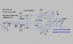
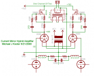
Basic concept is biasing up the Triode with a bypassed CCS.
That just happens to have the same drift as the Anti-Triode.
Its a little different than the "brute" version, but not much.
Still needs a big cap to bridge two low impedance nodes.
---------------------------------------------------------------------------
I'd probably choose to drive IN-, just because a gate won't
forward conduct. Cap on the CCS may "breathe" the same
no matter which input is overdriven, or not, I'm not sure.
balance in the face of temperature and other drifts.
I probably threw a few too many conservative tweak parts at it
than needed. If both FETs are on the same heatsink, probably
doesn't need the obsessive extra diode and 2R drop equalizers..
Basic concept is biasing up the Triode with a bypassed CCS.
That just happens to have the same drift as the Anti-Triode.
Its a little different than the "brute" version, but not much.
Still needs a big cap to bridge two low impedance nodes.
---------------------------------------------------------------------------
I'd probably choose to drive IN-, just because a gate won't
forward conduct. Cap on the CCS may "breathe" the same
no matter which input is overdriven, or not, I'm not sure.
Attachments
I just went overboard a little trying to equalize the power
dissipation of the two FETs, so they would drift equally.
Odd diode merely to drop the same as the BJT cascode's
emitter. That degree of voltage nitpicking went clearly
beyond the absurd. "Do Nothing" 2R on the Anti-Side is
in the same category.
Currents were already equal by design. If the voltages
idle the same, then we got equal power, equal heat,
equal drift... Blah Blah Blah etc etc....
")
Michael,
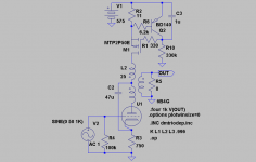
As we speak my friend Hoktuna is actually building the SE-version:
Then we can easily move the cap to try out the other possibility. Actually it was kenpeter who, in another thread, adviced me to move the cap. Moving up the currentmirror with an unbypassed R below as kenpeter suggests could also be an option.
As we speak my friend Hoktuna is actually building the SE-version:
An externally hosted image should be here but it was not working when we last tested it.
Then we can easily move the cap to try out the other possibility. Actually it was kenpeter who, in another thread, adviced me to move the cap. Moving up the currentmirror with an unbypassed R below as kenpeter suggests could also be an option.
Attachments
kenpeter said:I just went overboard a little trying to equalize the power
dissipation of the two FETs, so they would drift equally.
Odd diode merely to drop the same as the BJT cascode's
emitter. That degree of voltage nitpicking went clearly
beyond the absurd. "Do Nothing" 2R on the Anti-Side is
in the same category.
Currents were already equal by design. If the voltages
idle the same, then we got equal power, equal heat,
equal drift... Blah Blah Blah etc etc....
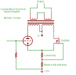
This is a nice variation on the circuit. Other possibilities are
bypassed resistor and shunt regulator, but the CCS keeps
good balance.
I think the circuit would operate much the same with the BJT
removed, but the cathode is a convenient upper control terminal
reference voltage for the cascode (very clever), which will also
improve the dynamic performance. Edit: of course, the cascode
itself equalizes the dissipation and keeps the drift between
MOSFETS within reason.
The bypassed CCS will have a time constant and will allow the
cathode voltage to increase under large-signal conditions as
needed to keep the average current at Cset. The tone burst
response will be such that the average current through the
tube will be greater than the average current through the
mirror early in the burst, the extra current going through the
capacitor into R until the cap charges and the tube average
current drops to 1/2 the total. at this point, the midpoint of
the tube's grid signal will have moved downward on the load
line. When the tone burst ends, the cathode will return to
the quiescent value at the time constant of the RC formed
by cathode impedance and C.
Maybe the time constant would need to be tuned, but this
looks like a viable design.
Lars:
The voltage drop across your 750R will moderate the current
shift with signal level and will be between a fixed bias scheme
and the above.
Another place to put the self-bias is under the constant current
common node. This scheme would require an OPT with a small
air gap.
Michael
Attachments
revintage said:Michael,
As we speak my friend Hoktuna is actually building the SE-version:
Then we can easily move the cap to try out the other possibility. Actually it was kenpeter who, in another thread, adviced me to move the cap.
Oops, our posts crossed. This is very interesting as you can
compare to see if the sound is improved or degraded by activating
the drive on the current mirror. One thing, though, is that turning
on the mirror drive raises the load impedance seen by the triode
by a factor of 2. I think you would need to change transformer
ratios or secondary taps to get a direct comparison. Both versions
should have the SE harmonic structure.
Michael
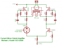
Synthesis of parallel + totem pole
I think the totem pole loads may be a good solution to DC balance
the dead-simple signal mirror. Any slight unbalance in this circuit will
be carried by the OPT, but it should be very small if the CCS all drift
together. Cascodes would probably be a worthwhile refinement.
The tube sees load equivalent to the impedance across the entire
primary, 5K in this example, since the circuit operates in class A and
the load is shared 50/50 across the ends of the totem pole.
I think it's statically and dynamically stable, preserving the large-
signal asymmetric current swing of the triode throughout.
Time to clear off the workbench again...
Michael
PS it's a lot like Don's #3 but should be DC-stable without adjustments
http://www.diyaudio.com/forums/showthread.php?postid=638009#post638009
Attachments
I would think twice before building that latch.
Suppose the differential Antitriode feels it's side isn't quite
pulling its fair share of DC total current? It draws DC across
the OPT, and lowers V-Plate. Now the Triode's plate will draw
less current, and the differential anti-triode feels even more
strongly that it isn't pulling its share. etc. etc. meltdown.
Or just as easily latch the other way. Maybe your triode gets
the full 80mA? The differential Antitriode would go into total
shut down. What brings it out of this?
Let me be clear which anti-triode I speak of as the "differential".
The anti-triode on the lower right, sitting just below the totem
ANTI-anti-triode. And not the totem anti-triode on the top left.
Clear as mud? I thought so...
I think I would want to halve the totem resistors and DC ref
the totem gates to the lower plate and drain. Even this may
not yet be fully DC stable? I havn't quite wrapped my head
completely around this problem yet.
Too bad I don't actually know how to use LTSpice's ability to
sim this circuit. Much less pretend there is a drift? For me, its
just a nifty drawing utility. You might ask Rev if he can sim for
latchup with tail slightly too big / tail slightly too small.
Yup, it's indeed (bi)stable. I was thinking only about side to side imbalance
going through the OPT.
More thought is clearly needed, but the intention was to create a balanced
current-swing across the bridge with any slight imbalance pulled across the
OPT. May not be practical other than with 2 tubes on the bottom, the way I'm
building my next big amp...
Thanks and sorry for the distraction...
Michael
Now you could Stack-ode the Triode side to double the apparent
plate action at the OPT. And that would give you a cascodelike
node to inject some DC tweakage onto the Triode's plate?
If I come up with anything that doesn't seem half baked, I'll draw
up a schematic of it or whatever... Meanwhile don't take the idea
too seriously.
I am dealing with fatigue from 3 days of intense Labview training.
Why not going vertical? But this one isn´t DC free.
http://www.diyaudio.com/forums/attachment.php?s=&postid=1617108&stamp=1222267648
It makes the MOSFET CCS work as an anti-triode. You will get ca 7W with one 6B4G!
http://www.diyaudio.com/forums/attachment.php?s=&postid=1617108&stamp=1222267648
It makes the MOSFET CCS work as an anti-triode. You will get ca 7W with one 6B4G!
I'm still figuring out how the drive works on the vertical one. DC
balanced is OK, DC free is not required.
Here's the context from which the most recent abortion is drawn.
This is a 32 watt per channel 300B amp, using a totem pole per side.
I thought I could either go parafeed or allow the OPT to carry a little
imbalance.
Michael
balanced is OK, DC free is not required.
Here's the context from which the most recent abortion is drawn.
This is a 32 watt per channel 300B amp, using a totem pole per side.
I thought I could either go parafeed or allow the OPT to carry a little
imbalance.
Michael
Attachments
Through the listening glass backwards??? A functioning
anti-triode automagically anti-mirrors its own current
flow the exact opposite of any delta seen at the Triode.
Yet top circuit end of VERTOR looks awfully constant...
May be listening the wrong reference to be an evil anti-
mirror of anything happening at the Triode. Only seems
able to detect is its own self referenced silence. I'm not
sure of any twisted mechanism by which it would ever
mutate fully into Mr Hyde. Needs... more... lightning...
- Home
- Amplifiers
- Tubes / Valves
- Spud-Assist: Totem-Pole Current-Mirror PP Hybrid