Or; 1.5 watts from a 417A spud amp.
Here is a concept I've been playing with, which is a current-mirror
circuit using totem-pole (series push-pull) topology. The idea is to
drive an active load so as to produce a current swing into the
external load exactly opposite the amplifier tube signal current
swing, thus dividing the load between the amplifier tube and the
active load.
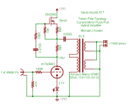
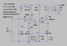
In the test amplifier schematic below, a 417A is used as the amplifier
and a DN2540 is the active load. The 68R resistors on either side of
the external load connection function as the AC load current divider
between the bottom device (tube) and top device (MOSFET). The top
68R also sets the idle current as per CCS. In practice, there is a little
loss due to the finite Gfs of the FET, and the R values can be tuned
for a load split > or < than 50/50 between tube and MOSFET.
When the tube is driven to greater conductance, current is sunk from
the load and the voltage drop across the lower 68R increases,
causing the MOSFET conductance to decrease by a proportionate
amount. Likewise when the tube is driven to less conduction, the
voltage drop across the lower 68R decreases, causing a
corresponding increase in MOSFET conduction, sourcing current into
the load.
In this way, the tube sees only a fraction of the load (here it's about
1/2) as the tube and MOSFET are basically in AC parallel driving the
output transformer. The tube sees about 4K anode load in this circuit
(actually closer to 3.5K due to the above mentioned loss).
There is an advantage over SRPP in that the signal current swing is
balanced for any external load. This makes it a good driver for
reactive loads, like the headphone/miniwatt amp here. Current
source capability could make it a good driver for an A2 power stage.
It's also a way to get better anode efficiency from CCS loaded
parafeed circuits.
When I get more time, I'll make some measurements of distortion
etc. but it's mostly f2 until you get over 1 watt, then some f3 and
above show up.
I'm actually able to get 10V p-p into 8 ohms (1.5 watts) by driving the
417A grid positive. The current mirror works fine into A2 as it senses
anode current and just follows the tube.
Michael
Here is a concept I've been playing with, which is a current-mirror
circuit using totem-pole (series push-pull) topology. The idea is to
drive an active load so as to produce a current swing into the
external load exactly opposite the amplifier tube signal current
swing, thus dividing the load between the amplifier tube and the
active load.
In the test amplifier schematic below, a 417A is used as the amplifier
and a DN2540 is the active load. The 68R resistors on either side of
the external load connection function as the AC load current divider
between the bottom device (tube) and top device (MOSFET). The top
68R also sets the idle current as per CCS. In practice, there is a little
loss due to the finite Gfs of the FET, and the R values can be tuned
for a load split > or < than 50/50 between tube and MOSFET.
When the tube is driven to greater conductance, current is sunk from
the load and the voltage drop across the lower 68R increases,
causing the MOSFET conductance to decrease by a proportionate
amount. Likewise when the tube is driven to less conduction, the
voltage drop across the lower 68R decreases, causing a
corresponding increase in MOSFET conduction, sourcing current into
the load.
In this way, the tube sees only a fraction of the load (here it's about
1/2) as the tube and MOSFET are basically in AC parallel driving the
output transformer. The tube sees about 4K anode load in this circuit
(actually closer to 3.5K due to the above mentioned loss).
There is an advantage over SRPP in that the signal current swing is
balanced for any external load. This makes it a good driver for
reactive loads, like the headphone/miniwatt amp here. Current
source capability could make it a good driver for an A2 power stage.
It's also a way to get better anode efficiency from CCS loaded
parafeed circuits.
When I get more time, I'll make some measurements of distortion
etc. but it's mostly f2 until you get over 1 watt, then some f3 and
above show up.
I'm actually able to get 10V p-p into 8 ohms (1.5 watts) by driving the
417A grid positive. The current mirror works fine into A2 as it senses
anode current and just follows the tube.
Michael
Attachments
I see exactly what you are driving at. Bottom triode sees a
constant current source, and xfrmr primary in series with 68R.
The plate swing is close but not quite exactly Mu due to the
non-infinate loading.
Top Depletion MOSFET follows the plate, and also drives the
primary thru 68R, the low 68R is seen as very high impedance
because the plate beneath it is at the same AC potential.
Very similar load as what the triode below is seeing.
The sum of currents (measured by the pair of 68R's) is always
held constant (whatever voltage drop turns on the MOSFET).
Thus the MOSFET on the top of the totem is operating in true
Anti-Triode emulation mode.
The output signal is quasi-SE, as the antitriode pulls with the
curvature bent backward of a "normal" complimentary device.
Hi Ken,
> Should the OPT have pathed directly back to the cathode?
> Instead of including the bias LED into the output's loop?
I thought about that, but then the load current sourced from the
MOSFET would be returned through the LED. "Currently" the LED
sees the tube's share of the load. It's going to be in one loop or the
other and it's always in the input loop, so I thought it best to keep
in in the tube path and out of the MOSFET path.
> The plate swing is close but not quite exactly Mu due to the
> non-infinate loading.
Lightly loaded, as in a drive stage, this is true.
The load line seen by the triode will be defined by approximately 2X
the load impedance for equal value resistors. There is some leeway
to split the load unequally which is what I plan to experiment with
next. I want to try a 100R anode resistor and split the load 60/40.
Should be a little better damping factor, gain, and output swing.
The 417A is rated for 4.5 watts anode power and at that the anode
takes on a dull red glow... So I can abuse sand and tubes at the
same time!
Cheers,
Michael
Attachments
looks familiar
http://www.diyaudio.com/forums/showthread.php?postid=638005#post638005
Since Ken later referenced the O'Schade article on square law tubes due to g1 island effect:
http://www.diyaudio.com/forums/showthread.php?postid=1516035#post1516035
I would guess now that the finite Fet loop gain is not going to cause much of a problem, since both devices are approx. square law. So maybe a little 2nd harmonic cancellation, but mostly the triode signature is going to be left intact.
Michael:
"When I get more time, I'll make some measurements of distortion
etc. but it's mostly f2 until you get over 1 watt, then some f3 and
above show up."
Should be interesting results, "sounds" like its on the right track.
I'm thinking now whether there could be any utility in using a pentode on the bottom with screen grid feedback to get triode sound. So far its just degenerating into a pentode wired triode or a source follower off the plate driving the screen grid (with a little DC drop), a little more thinking required. Idea would be to eliminate the Fet drive from the output altogether if possible.
Don
Hi Don,
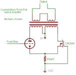
All variations on the same theme of complementary current drive.
I have built two amps based on the idea, trying to further simplify.
I'm cooking an H-bridge parafeed now that looks like your #3, but
with both triodes on the bottom. Looking for >30 watts from a pair
of 300B run conservatively.
I'm trying to see how simple I can make the circuits, got rid of
the op-amps and finding that the slight nonlinearity of the
MOSFET is not an issue as you say.
Here's a twist on #1 that probably can't get much simpler.
I'm going to repurpose my old anti-triode amp to test it.
Cheers!
Michael
Attachments
That certainly is simple, which makes it attractive - and PP power from a single ended input. But how much problem will thermal issues be, due to the different affect on the transfer characteristics of the two devices? A class A amp should reach something close to a steady state, but that will vary with ambient conditions too. That should be manageable if the transformer can tolerate some imbalance. What about signal induced transients?
Sheldon
Sheldon
Great points, Sheldon!
I expect some kind of diode string might help keep the relative
g-s voltage constant over temp. The tube Iq will drift also, so
I thought maybe a CCS on the B+, but CCS in series with the
inductance of the OPT makes it a noise catcher at best...
needs some fiddling with bypass caps, etc.
The other issue you mention is the real reason I'm going forward
with the series totem pole toplology for the moment.
The parallel circuit with OPT is stable in a steady-state sense but my
experiments with high loop gain (op-amps) in the current feedback
path show some instability under music conditions. I put that
investigation on the back burner but I believe it's the problem of
the MOSFET current coupling to the input loop through the common
current sensing resistor. I think there is a positive feedback loop
under some conditions I have yet to understand. Maybe it's just
due to the op amp gain and the simpler circuit will not have the
problem.
Also think I may go with an enhancement mode MOSFET and an
adjustable gate voltage, and in a practical amp a cascode may
work better.
Basically, I decided to think about things for a while and go
stupid simple to start with, and add only what's found to be
needed through testing and listening.
Michael
Michael Koster said:Basically, I decided to think about things for a while and go
stupid simple to start with, and add only what's found to be
needed through testing and listening.
I like that, if for no other reason than I have better intuitive understanding of simple stuff. Might as well try the simplest possible, just might be OK. A cascode would take the heat off (so to speak) of the controlling FET.
Or, instead of a diode, could you use the same FET with gate tied to drain, for compensation?
Sheldon
Sheldon said:...due to the different affect on the transfer characteristics of the two devices?
Doesn't matter the transfers are completely different.
In fact these hybrids DEPEND on them being different.
Whichever device is "superior" in gm will slave itself
to become the anti-transfer of the weaker device.
If the Triode were the higher in gm, it would become
an anti-FET... Fortnately for us, there is no contest.
Our MOSFET here will surely become the fearsome
Anti-Triode, as women and children run screaming
through the streets in a blind panic.
You could just as easily ground the Triode's grid, feed
signal to the MOSFET's gate, and the circuit would still
behave Triode/ Anti-Triode. Bizarre as that seems.
Balanced amplifiers fudge new transfers for both devices
in some imaginary la-la-land between the original and
the anti. We aren't going anywhere near there today.
We are staying firmly in the gutter on the other side of
Triode alley. Where whiskey flows as a superconductor,
and push-pull effectively becomes parallel.
The "simplest" way to equalize the long term currents in
both branches is to have separate cathode and source
resistors. And brute force bridge those two low impedance
nodes together with a huge electrolytic cap or two... I am
not saying that would sound very good.
----------------------------and by the way------------------------
gm for the CK5842 Triode (417A) = 27 mMho
gm for the DN2540 Depletion FET = 325 mMho
You would have to parallel or current mirror many many
more such triodes before the MOSFET's anti-behavior
started to poison the mix.
kenpeter said:Doesn't matter the transfers are completely different.
In fact these hybrids DEPEND on them being different.
My question was regarding their temperature response. As the temperature of the FET rises, the bias point will change and the current will decline somewhat. Enough to be an issue? It doesn't look like much from the data sheets, but the graph resolution at currents likely to be used in this application is not revealing.
Sheldon
Michael:
"When I get more time, I'll make some measurements of distortion
etc. but it's mostly f2 until you get over 1 watt, then some f3 and
above show up."
---------------------------------------------------
smoking-amp:
Should be interesting results, "sounds" like its on the right track.
I'm thinking now whether there could be any utility in using a pentode on the bottom with screen grid feedback to get triode sound. So far its just degenerating into a pentode wired triode or a source follower off the plate driving the screen grid (with a little DC drop), a little more thinking required. Idea would be to eliminate the Fet drive from the output altogether if possible.
---------------------------------------------------
Yes, I will also wait for such results.
This rather 'simpe' way to arrange one single stage power amp
with use of suitable standard Power Supply Transformer as output,
is very attractive to me.
One True DIY Tube amplifier when as best to get us builder going
")
regards
"When I get more time, I'll make some measurements of distortion
etc. but it's mostly f2 until you get over 1 watt, then some f3 and
above show up."
---------------------------------------------------
smoking-amp:
Should be interesting results, "sounds" like its on the right track.
I'm thinking now whether there could be any utility in using a pentode on the bottom with screen grid feedback to get triode sound. So far its just degenerating into a pentode wired triode or a source follower off the plate driving the screen grid (with a little DC drop), a little more thinking required. Idea would be to eliminate the Fet drive from the output altogether if possible.
---------------------------------------------------
Yes, I will also wait for such results.
This rather 'simpe' way to arrange one single stage power amp
with use of suitable standard Power Supply Transformer as output,
is very attractive to me.
One True DIY Tube amplifier when as best to get us builder going
regards
 ?
?
re: revintage
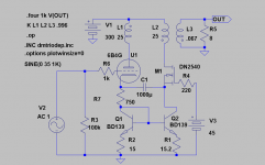
Might want to put a cap from Q1,Q2 bases to ground so that the current mirror acts only on the DC current. Would seem to be a nice way to control the assymetric buildup of current at high level by the triode due to its non-linearity. ie., keeping the xfmr balanced on average. Still would need to check whether the DC current control time constant causes any audible "breathing" effect after loud audio bursts.
Don
revintage:
It took me a little while to recognize that the inverse current
mirror AC signal is passed by the AC parallel combination
of R1 and R2. This is acting like the common bottom resistor
in my "oversimplified" circuit but the current mirror keeps DC
current balanced between MOSFET and tube. Nice idea!
Something still nags me about the current mirror though.
Is the "effective" R 15 ohms or 7.5 ;-)
Don:
I think bypassing the AC to ground at the R1R2 node would
have the same effect as removing R1 and R2 signal-wise. They
seem to be needed to drive the MOSFET source with the
mirror of the signal current, cascode-style. This works like
Ken's brute force circuit with the big cap across the pair of
CCS but maintains DC balance at the same time.
Don has also pointed out one issue with auto DC balance
control in that it has to have a cutoff frequency to stay out
of the audio range. This puts it into the range of what I call
the "distortion current", the output stage current that follows
the musical dynamics (due to asymmetric mu of triodes).
Your cutoff frequency is determined by the C1 and the
impedance in the cathode-source circuit. Passing a tone
burst signal through the stage will reveal the magnitude
of the distortion current (becomes a step function with
the tone burst) and your balancer response. I'm still not
sure how much of a problem it will be.
From a quick look it appears it will work. But your sim already
shows that... I guess I need to get my spice program running
so I can follow along with some of these.
Michael
Michael:
"I think bypassing the AC to ground at the R1R2 node would
have the same effect as removing R1 and R2 signal-wise. They
seem to be needed to drive the MOSFET source with the
mirror of the signal current, cascode-style. This works like
Ken's brute force circuit with the big cap across the pair of
CCS but maintains DC balance at the same time."
The 750 Ohm resistor on the left end of C1 should allow the AC voltage to vary and transfer thru C1 to the Mosfet source. The right end of C1 sees only the hi-Z end of the current mirror and the Mosfet source for loading. So the added cap from bases to Gnd should allow operation yet. The 15 Ohm R1 and R2 will be shunted out AC wize though. Does indeed look like Ken's brute force circuit, with the current mirror added now to balance DC.
Don
smoking-amp said:Michael:
...
The 750 Ohm resistor on the left end of C1 should allow the AC voltage to vary and transfer thru C1 to the Mosfet source. The right end of C1 sees only the hi-Z end of the current mirror and the Mosfet source for loading. So the added cap from bases to Gnd should allow operation yet. The 15 Ohm R1 and R2 will be shunted out AC wize though. Does indeed look like Ken's brute force circuit, with the current mirror added now to balance DC.
Don
Duh, thanks Don!
I guess I still didn't understand it. I think I ignored the 750R
because I have some circuits like that where it is used for bias
only. That's what was bugging me about the resistors under
the current mirror. The effective R is 750 ohms.
This looks like a pretty good way to handle the DC balance issue,
except for needing a big cap to pass cathode current across. It
also has the stability of self-bias.
The Cathode-Current-Mirror-Mosfet-Cascode-with-Brute-Force-
Cathode-Signal-Coupling
The fc is probably based on 2X the cathode impedance,
because the MOSFET is reflecting cathode impedance and
placing it in series with the tube's cathode impedance.
The large signal burst behavior should be something like:
At the beginning of the tone burst the Big Cap has a certain
charge, the MOSFET exactly mirrors the inverse signal
current and the total current for the stage stays the same.
As the tube swings into higher conduction, higher gm, the
MOSFET exactly opposes it, and when the tube goes into
lower conduction, smaller swing half-cycle, the MOSFET
exactly opposes it with a smaller swing. (This is the so-
called evil antitriode curve...) The tube goes +40ma, the
MOSFET goes -40mA... tube goes -33mA, MOSFET goes
+33mA. The current draw from the power supply is constant
...until the Big Cap starts to charge due to the asymmetric
current swings. As the Big Cap charges a little more on each
large-swing cycle, the current through the stage increases
a little more, until an equilibrium is reached where the load
line re-centers at a higher current, lower voltage midpoint.
When the tone burst ends, the DC current drops at the
same time constant.
Now consider the OPT magnetization. During the first part
of the tone burst, there is a DC magnetization current in the
core (just like there is a charging current in the Big Cap) due
to the asymmetric swing. As the Big Cap charges and the total
current increases, the DC magnetization current in the core
decreases.
Now here is where I believe it may be better to gap the core
for a small offset because the while the balancer is seeking
a new point, there will be DC in the OPT core. One will need
to make the balancer operate at a time constant short enough
to avoid saturation i.e. almost in the audio band to avoid
needing to gap the core. This may actually be a good sounding
approach because it will likely not be heard as a pumping or
similar artifact (see related discussions on PS filter time
constants) i.e. the amp may sound "faster" whatever that
means ;-).
However, I want to explore another approach which does not
try to balance the DC continuously but rather gap the core to
allow the large-signal offset to persist indefinitely. This removes
the time constant completely. A small gap sufficient for this is
already built into most P-P OPTs anyway.
Then I would like to compare the 2 approaches to see if I can
hear a difference. I suspect that tuning the balancer will be
pretty much like tuning a parafeed cap; there will be a sonically
acceptable sweet spot, and that automatic balancing in current
mirror amps is a Good Thing. How small can the Big Cap be for
good audio response?
revintage:
I hope you build this or something like it and give it a try. 8W from
a 2A3 with SE sound is good. I think it's almost like a perfectly
matched PSE in a way.
By the way, I would check the peak voltage on each side of the
transformer primary to see if a 120/240V line toroid can handle
it without saturation at 20 Hz. You may need a transformer for
a higher peak voltage.
Don:
Maybe all of those SE OPTs can be repurposed to serve as filter
chokes for power supplies in tank-built preamps. It would save
the dumpster walls getting dented ;-)
Cheers,
Michael
- Home
- Amplifiers
- Tubes / Valves
- Spud-Assist: Totem-Pole Current-Mirror PP Hybrid