Hi all,
I'm having trouble understanding how the cathode bias circuit recommended for the Aikido line stage is implemented. I thought that cathode bias was to raise AC voltage up so the negative swing was above zero. The scheme I'm working with references it to 1/4 B+ voltage. Here's the excerpt that is confounding me: "...since one triode stands atop another (in the same envelope), both triodes can never share the same heater-to-cathode relationships."
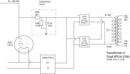
I have 2 dc regulator boards feeding tube heaters, I had originally planned on each board serving the tubes for each channel. I'm wondering now if I can merge both dc boards as one supply, insert the cathode bias circuit, and then on to my tubes. Here's a diagram, what are your thoughts?
gary
I'm having trouble understanding how the cathode bias circuit recommended for the Aikido line stage is implemented. I thought that cathode bias was to raise AC voltage up so the negative swing was above zero. The scheme I'm working with references it to 1/4 B+ voltage. Here's the excerpt that is confounding me: "...since one triode stands atop another (in the same envelope), both triodes can never share the same heater-to-cathode relationships."
I have 2 dc regulator boards feeding tube heaters, I had originally planned on each board serving the tubes for each channel. I'm wondering now if I can merge both dc boards as one supply, insert the cathode bias circuit, and then on to my tubes. Here's a diagram, what are your thoughts?
gary
Attachments
Actually the point of bias (whether cathode or not) is to make the DC potential of the cathode higher than that of the grid which sets the DC current through the tube. It will also determine how high and low the AC signal can go before serious distortion of course as too large a signal would drive the tube into grid current (grid higher than cathode) or cutoff.
I am not familiar with the context of your quote but I interpret what they are saying to be that since each tube has only one heater then if the same bottle is used for the top and bottom tube the potential between the heater and cathode number one can not be the same as that between that same heater and cathode number two. The only way to do that is to use one bottle for the top and another for the bottom and use two separate heater supplies.
You could use one bottle for the lower tubes in both channels and another for the upper tubes. Then use one DCPS for the top tube and the other for the bottom tube. The reference each one slightly higher than their respective tubes cathode so that rectifier and regulator hash is less likely to get into the audio.
I am not sure I understand how any of this would effect a cathode bias situation other than needing to know what you cathode voltage will be.
Your diagram makes me think you are looking at fixed bias however as you seem to be doing a voltage divider on the B+ which would not be needed for normal cathode bias. Maybe if you showed the entire circuit it might be more clear to me what you are trying to do.
I am also wondering why we are going to the trouble of DC heaters on a line stage.
Oh, wait, I think I see. What you have labeled as a cathode bias circuit is just the VD to reference the heater supplies. But you have both heater supplies tied to the same reference voltage... so are you using two just to get enough current capacity?
What you are calling a 'cathode bias' circuit in your diagram is actually a heater bias circuit, which will result in the heaters being elevated about 75v DC above ground. For a single 6SN7 doing duty as both the top triode and the bottom triode, this should be OK. The 6SN7 has a heater-cathode voltage rating of -200v to +100v, so 75v is a happy medium. You should increase the bypass cap in the heater bias circuit from 0.1uF to 10uF.
Gary,
What JB said about biasing the filament to 1/4 of the B+ is very much for those using his PCB. In his PCB, each tube is "wired" as the top and the bottom. If you are doing wire-to-wire, you can follow what Mike said - use one tube for the bottom triode of both channels, and another tube for the top triodes. This way, you only need to bias the top triode to whatever optimal B+ that the 6SN7's are happy; however, this also mean that you will need 2 filaments supplies which don't seem to be a problem to you")
Ray, JB uses a 0.1uF cap to bypass the heater bias to ground. I have seen people recommending up to 100uF. What is the reason that you use 10uF? I kind of don't quite understand the rationale of different capacitance and m curious the impact of different value to the circuit.
What JB said about biasing the filament to 1/4 of the B+ is very much for those using his PCB. In his PCB, each tube is "wired" as the top and the bottom. If you are doing wire-to-wire, you can follow what Mike said - use one tube for the bottom triode of both channels, and another tube for the top triodes. This way, you only need to bias the top triode to whatever optimal B+ that the 6SN7's are happy; however, this also mean that you will need 2 filaments supplies which don't seem to be a problem to you
Ray, JB uses a 0.1uF cap to bypass the heater bias to ground. I have seen people recommending up to 100uF. What is the reason that you use 10uF? I kind of don't quite understand the rationale of different capacitance and m curious the impact of different value to the circuit.
For me it's very slowly and not very surely. Thanks for the help guys. Ray, could you talk a little about the bypass cap, why 10uF instead of .1uF?
Heater bias is correct. My mistake, but won't that then elevate the heater to cathode voltage relationship equally for both triodes within the tube? How does this discourage electrons from moving from the cathode of one triode to the plate of the other? I assume that this is the point here. Is this what is referred to as hash?
gary
The current draw from that heater bias supply should be exceedingly low (close to zero in all but catastrophic cases). There is no good reason for excessive capacitance on that node, unless you have extra ginormous capacitors that you are looking to waste.
By the time you are dividing B+ for heater biasing, you are ideally already be starting with a very clean source voltage. The only extra noise you'll be seeing is directly from the resistors used in the divider chain, and even then all you're doing is using that voltage to reference an AC heater tap. If you notice it, I'll be surprised.
If I understand correctly, the real reason for that 0.1uF capacitor is to provide an AC ground for the heater reference. If there's a small amount of AC on the center tap (due to its not being precisely in the 'center'), it'll find an easy path to ground through that cap instead of perturbing your bias voltage or getting into B+.
-k
gary h [/i][B] why 10uF instead of .1uF? [/B][/QUOTE] The corner for with that resistor string and a 0.1uF cap will be about 20Hz said:won't that then elevate the heater to cathode voltage relationship equally for both triodes within the tube? How does this discourage electrons from moving from the cathode of one triode to the plate of the other?
No. You have one heater element, but two independent cathodes per dual triode. As mentioned earlier, if the triodes from one tube are stacked in the circuit (one on top the other, which is usually done with the Aikido so that you can independently change input and output tube types), then one cathode will be above the filament potential and one below. With a single tube, one usually raises the heater above the cathode, because that's slightly better, and easier, than having it lower. But having the heater at lower potential than the cathode is almost as good for noise cancellation. Example curves are floating around here somewhere.
This has nothing to do with electrons moving from one cathode to the opposite plate (which is very low, otherwise putting two triodes in a single envelope wouldn't work). This only concerns fluctuations in the heater potential from influencing the cathode.
Sheldon
Thank you all,
if I understand correctly then, all 4 heaters need to be referenced to a higher (or different) voltage (B+/4 in this case,) to function properly. This is regardless of the input/output tube topology of JB's design because once the signal leaves the first triode of a tube and returns to the second, it will have been elevated further by the B+ (in this case 300V.) Please correct me if I'm still not getting this.
Just out of curiosity, what happens (both electrically and musically) when the heater and the cathode are set at the same potential?
gary
10uF is the most commonly recommended value and it's what I use. I haven't experimented with 0.1uFRay, JB uses a 0.1uF cap to bypass the heater bias to ground. I have seen people recommending up to 100uF. What is the reason that you use 10uF?
In this case, the purpose of elevating the heater bias to 75v is because that will result in a safe heater-cathode voltage for each cathode. It has nothing to do with minimizing hum. If you exceed the specified maximum htr-cathode voltage, you run the risk of permanently damaging the tube through breakdown of the very thin insulation between heater and cathode. The 6SN7 is more forgiving than most but it has its limits.if I understand correctly then, all 4 heaters need to be referenced to a higher (or different) voltage (B+/4 in this case,) to function properly. This is regardless of the input/output tube topology of JB's design because once the signal leaves the first triode of a tube and returns to the second, it will have been elevated further by the B+ (in this case 300V.) Please correct me if I'm still not getting this.
If the heater potential is slghtly less than, or the same as, that of the cathode, you will probably notice no detrimental effect. This is the arrangement in the vast majority of amplifiers. However, in a high gain voltage amp stage early in the amplifier, there can be a problem of hum. This can usually be improved by elevating the heater potential until it's around 30v more positive than the cathode. This technique can be used to combat emission from heater to cathode, by making the former more positive than the latter, thus reducing hum pickup within the tube.Just out of curiosity, what happens (both electrically and musically) when the heater and the cathode are set at the same potential?
It's not a bypass cap, it's a filter cap.
The idea is to create a voltage divider with the two resistors and use the voltage at the centre tap of the divider as a reference point for the heater supply. It litterally offsets the whole heater voltage by that amount.
However there is no requirement for current to flow from the divider to the heater circuit as it is an offset / reference voltage only. Therefore a sturdy filter capacitor is added to the centre point of the divider to ensure that the varying current in the B+ line is filtered out and does not reach the heater circuit.
Make sure the voltage rating of the capacitor is sufficient. Most people seem to use a capacitor in the range 0.1 to 47 microFarad.
: )
The cap needs to be large enough to push the LF pole well below the mains frequency or other source of LF noise. It's really there just to provide a relatively low impedance for AC to ground. No B+ supply I have ever used was noisy enough for the decoupling to make one iota of difference for that reason.
- Status
- This old topic is closed. If you want to reopen this topic, contact a moderator using the "Report Post" button.
- Home
- Amplifiers
- Tubes / Valves
- cathode bias circuit question