After much reading and discussion, I think I've settled on the plans for an upcoming build for a single-ended 300B integrated amplifier.
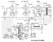
The circuit will be using 1/2 a 12AT7 input tube, a triode-strapped EL34 driver, and 300B output tube per channel, as per the following schematic:
- Rectification will be solid state.
- Power transformer will be custom wound locally to similar specs of the One Electron TFBT-1.
- Output transformers will be the One Electron UBT-2 4K8.
- Constant current source for the 1/2 12AT7 will be a BottleHead C4S.
- A single 10H 300mA Hammond choke will be used in the circuit.
- Optionally there may also be a mini-choke (~300mH) before the CLC filter.
- Aluminum foil paper in oil caps in the power supply stage
- Copper foil paper in oil caps in the signal stage
- Metal film resistors throughout
What do you guys think - does it look like a good plan? Any pointers or tips? Has anyone here perhaps built an amp using that schematic?
Thanks in advance,
X
The circuit will be using 1/2 a 12AT7 input tube, a triode-strapped EL34 driver, and 300B output tube per channel, as per the following schematic:
An externally hosted image should be here but it was not working when we last tested it.
- Rectification will be solid state.
- Power transformer will be custom wound locally to similar specs of the One Electron TFBT-1.
- Output transformers will be the One Electron UBT-2 4K8.
- Constant current source for the 1/2 12AT7 will be a BottleHead C4S.
- A single 10H 300mA Hammond choke will be used in the circuit.
- Optionally there may also be a mini-choke (~300mH) before the CLC filter.
- Aluminum foil paper in oil caps in the power supply stage
- Copper foil paper in oil caps in the signal stage
- Metal film resistors throughout
What do you guys think - does it look like a good plan? Any pointers or tips? Has anyone here perhaps built an amp using that schematic?
Thanks in advance,
X
Just a few suggestions/observations...First off the coupling cap to the 300B at 1uF @400VDC...this should be at full B+, a 630VDC would be safer.
The Humpot at 30 Ohms total is running at 66% rating, would you consider a 25-25 ohm @ 2W or higher?
Also the 20K 3W PWR resistor for your input stage is running at 50% rating....bump that up to a 5W also.
_______________________________________Rick.........
The Humpot at 30 Ohms total is running at 66% rating, would you consider a 25-25 ohm @ 2W or higher?
Also the 20K 3W PWR resistor for your input stage is running at 50% rating....bump that up to a 5W also.
_______________________________________Rick.........
EL34 in triode mode needs to be run much hotter than 200V/17mA. Have a look at the triode mode curves in the older Mullard data sheet - the low-current curvature sets in at 25mA and is pronounced at 17. If you can't run it at around 60mA (and it seems odd to run as much currrent in the driver as the endtriode), then try the 6V6.
Actually, I have not found the ultra-strong grid-driver to be worth the trouble in 300Bs. The best sound for me is with pentode-connected EL84 (VG2 = 150V) or IF pentodes, with about 15K load - only one stage needed from CDP to 300B.
300B Grid coupling: beware going above 220K grid-to-cathode resistance. Coupling cap should not be oversized, 0.1uF should do - and before spending plenty cash on PIO caps - try the cheap LCR film/foil 1000V polypropylene (type PC/HV/S/WF), which in this position sounds superb. Be sure to use the S version, designed for fast risetime.
http://www.lcrcapacitors.co.uk/cap7.pdf
Power supply is critical for SE 300B circuits. Spend money here rather than on caps! I prefer the sound & slow warm-up of valve rectifiers in SE design. If you really don't want the hassle, use UF4007s in a bridge, well-snubbed using the PC/HV/S again (0,22uF plus 47 ohm as a starter) and be sure to use an NTC to limit the cold current, and run the DHT heat from separate trafo, so you can sequence heat before B+ arrives.
One choke between two channels is asking too much. Remember the power supply rejection is periliously small in SE circuits, and two big valves on one supply can also be LF-unstable, especially with your modest-value supply caps.
For the GD, Sovtek and other lower cost 300Bs especially, you'll find that current driven heating is the most cost effective upgrade you can make on these SE amps.
Metal film resitors are OK, but their inductive properties make them shrieky in some positions. The thick-film TO-220 resistor are worth the extra in the driver anode, at least, and chip resistors are nonmagnetic & good in grid circuits.
If you want better sound, replace the 12AT7 with an ECC40 and replace the EL34 with a 46.
The 46>300b is a killer combination, alternatives being 10y>300b and 71a>300b. These are tried and tested.
I continue to find the ECC40 the best of the small signal indirectly heated tubes. Rimlock socket has fortunately insured that plenty of stocks are available on ebay from Germany, France etc. Otherwise it would probably be hoarded by everyone and cost $100 or more.
Andy
First off let me say a big thanks for the responses.
I wanted to mention that the builder and I want to stick as close to the schematic as possible - would not want to change too much. That said, I appreciate the input on the caps/resistors etc. and will certainly take those on board. But, we would not look to change the tube complement, at least at this stage.
Also just to mention - my technical understanding is very limited, and what I know is just what I have learned in the past 2-3 weeks of reading after initiating the project. So it is the first time looking at, reading, discussing tube circuits so please bear with me
Thanks - yes I have received a number of suggestions to change that to 600V plus.
The feeling I got was that the 12AT7 and 17mA would be fine for the EL34; and that the EL34 won't be run anywhere near max but enough to drive the 300B. I think the CCS was put there to help stabilize the circuit? They did, however, also say that the 6L6 would be a nice substitute to roll in at some stage. Would any of the circuit components need to change if I wanted to experiment - that is, would any of the caps/resistors need changing or would the 6L6 be a direct drop-in?
Is that perhaps why I was recommended (on another forum) to use a mini-choke before the CLC filter (to clean up the power supply with minimal effect on the B+ voltage)? My technical understanding unfortunately does not extend that far
Also for the main choke, would the large 10H 300mA rated Hammond not be sufficient? My builder mentioned that we needed 10H 220mA, so the Hammond should be within that requirement.
Cheers,
X
I wanted to mention that the builder and I want to stick as close to the schematic as possible - would not want to change too much. That said, I appreciate the input on the caps/resistors etc. and will certainly take those on board. But, we would not look to change the tube complement, at least at this stage.
Also just to mention - my technical understanding is very limited, and what I know is just what I have learned in the past 2-3 weeks of reading after initiating the project. So it is the first time looking at, reading, discussing tube circuits so please bear with me
Richard Ellis said:Just a few suggestions/observations...First off the coupling cap to the 300B at 1uF @400VDC...this should be at full B+, a 630VDC would be safer.
Thanks - yes I have received a number of suggestions to change that to 600V plus.
Rod Coleman said:EL34 in triode mode needs to be run much hotter than 200V/17mA. Have a look at the triode mode curves in the older Mullard data sheet - the low-current curvature sets in at 25mA and is pronounced at 17. If you can't run it at around 60mA (and it seems odd to run as much currrent in the driver as the endtriode), then try the 6V6.
The feeling I got was that the 12AT7 and 17mA would be fine for the EL34; and that the EL34 won't be run anywhere near max but enough to drive the 300B. I think the CCS was put there to help stabilize the circuit? They did, however, also say that the 6L6 would be a nice substitute to roll in at some stage. Would any of the circuit components need to change if I wanted to experiment - that is, would any of the caps/resistors need changing or would the 6L6 be a direct drop-in?
Rod Coleman said:One choke between two channels is asking too much. Remember the power supply rejection is periliously small in SE circuits, and two big valves on one supply can also be LF-unstable, especially with your modest-value supply caps.
Is that perhaps why I was recommended (on another forum) to use a mini-choke before the CLC filter (to clean up the power supply with minimal effect on the B+ voltage)? My technical understanding unfortunately does not extend that far
Also for the main choke, would the large 10H 300mA rated Hammond not be sufficient? My builder mentioned that we needed 10H 220mA, so the Hammond should be within that requirement.
Cheers,
X
The EL34 will run at the settings in your drawing, but the distortion will be unecessarily high, because the EL34 needs to run at least 30mA to escape the curved (distorted) region of its characteristic. It'll work, but not sound as good as it should.
Same thing with the choke really. You can make it work, but a power supply for each side is worth the investment! For SE circuits most especially, the power supply is the area that repays the time spent in design, and paid out on high quality transformers, chokes, caps. - probably in that order!
Same thing with the choke really. You can make it work, but a power supply for each side is worth the investment! For SE circuits most especially, the power supply is the area that repays the time spent in design, and paid out on high quality transformers, chokes, caps. - probably in that order!
Rod Coleman said:The EL34 will run at the settings in your drawing, but the distortion will be unecessarily high, because the EL34 needs to run at least 30mA to escape the curved (distorted) region of its characteristic. It'll work, but not sound as good as it should.
Much appreciated. So running something like the 6L6 in its place should provide sufficient power to the 300B but without the unneccessary distortion? If so, two quick questions:
- other than the 6L6, any other pentodes you suggest after the 12AT7?
- if I wanted to use a 6L6 in place of the EL34, would I need to change any parts/ratings of components in the circuit?
Cheers,
X
The 6V6 will fit the same socket as the EL34/6L6. It uses less heater power than either of them, and is usually cheaper. The new production JJ 6V6S is a beauty.
Set the cathode resistor to 430 Ohm 3 Watt, and the anode resistor to about 6.2K 20W TO-220 type film. This should run the 6V6 at about 250V 35mA for reasonably low distortion, and very high drive.
when you start it up, check that the cathode voltage of the 6V6 is about -15V.
have fun building!
Set the cathode resistor to 430 Ohm 3 Watt, and the anode resistor to about 6.2K 20W TO-220 type film. This should run the 6V6 at about 250V 35mA for reasonably low distortion, and very high drive.
when you start it up, check that the cathode voltage of the 6V6 is about -15V.
have fun building!
- Aluminum foil paper in oil caps in the power supply stage
I suggest ASC Oil-Filled Polypropylene, very good sounding PS cap if you have enough space.
- Copper foil paper in oil caps in the signal stage
Before you decide which one to use, check the fail rate of each brand.
Just go to www.audioasylum.com and search the name of the brand.
.33 and 1.0 mf oil capacitor is too expensive to throw in to a bin.
- Metal film resistors throughout
I suggest Non-Inductive Wire Round Resistors like Mill throughout the amp but in some position
for example cathode resistors of the pre tube and grid resistor you may use Riken or Audionote.
Metal film will throughout the amp will make ur SET amp sound like solid-stage amp. If you like that why not build gainclone instate.
Anyway, I feel that the schematic you are going to build is too expensive to make it good.
I would choose 2 stages or 3 stages direct coupling with higher quality parts and tube rather than your schematic.
My 300B amp is using 6SN7 direct coupling schematic, very simple schematic but high quality part and tube such as Dact step, High Quality PIO capacitor, NOS 6SN7 tube, High Quality OPT and Power trans can make this amp sound so good compared to complex schematic with average quality parts.
I prefer KISS policy (Keep It Simple Stupid) ^_^".
Rod Coleman said:Set the cathode resistor to 430 Ohm 3 Watt, and the anode resistor to about 6.2K 20W TO-220 type film. This should run the 6V6 at about 250V 35mA for reasonably low distortion, and very high drive.
Thanks for the input! I actually got a very interesting reply to the question of using the EL34 from one of the guys at BottleHead. I do not have the technical knowledge to be able to comment on what anyone is saying really so I thought I'd just post it up here
I looked at the EL34 operating point (222v plate, 20v cathode, 23mA current, 8.4K load impedance) and it looks very good to me. Actually, it looks like about 17v on the cathode - a bias resistor of 740 ohms or near that would be appropriate (it's not listed on the schematic). The high load impedance exactly counters the low current, and the distortion at maximum output will not be any different than if you ran it at higher current. However, this lower-current operating point allows greater voltage headroom - the EL-34 should be able to drive +/-140v to the 300B grid, nearly twice the required minimum - so at full drive voltage of +/-80v the distortion will actually be lower. (You could run 50mA with a 4K load resistor, but the available drive would be +/-100v, barely enough.)
The EL34 has a gain of 10, so the 12AT7 has only to provide
+/-8v or so to the EL34. There should be no difficulty driving
the Miller capacitance of the EL34.
5150ed said:Anyway, I feel that the schematic you are going to build is too expensive to make it good. I would choose 2 stages or 3 stages direct coupling with higher quality parts and tube rather than your schematic.
I also want to keep it simple, and it is kind of difficult as I don't have the ability or experience to read a schematic and say yay or nay
Do you perhaps have the schematic you used? Your amp sounds similar to one of the amps I thought of "mimicing": the Cayin A300B. I do not have a schematic unfortunately which makes it rather difficult to copy, but the description is:
The high-level input signal is directed to a 100k ohm volume potentiometer, from whence it's capacitively coupled to the grid of a 6SL7 dual-triode cascade, for pure voltage gain. The final plate of that tube drives the grid of a 6SN7 dual triode, configured as a cathode follower for low impedance. The full waveform then goes to the grid of a 300B output triode.
Cheers,
X
I scarcely want to get into a cross-forum debate about operating points - but two things:
- the EL34 is normally operated at 400V or more, with an idle current of 30mA or more. The Mullard recommended operating point for lowest distortion (in push-pull) is 370V/70mA. This dissipates a lot of power, but that's necessary to get the distortion down.
If that does not convince you, simply look at the Mullard triode-mode curves! At the 70mA suggested by Mullard, the curves are relatively straight and parallel. They get curved and compressed as you drop down from that current level - at 20mA the effect is huge, and that translates into distortion.
Really though, you would be better to ignore all these conflicting arguments and just build and listen! Try the starved EL34 driver and see for yourself.
- Status
- This old topic is closed. If you want to reopen this topic, contact a moderator using the "Report Post" button.
- Home
- Amplifiers
- Tubes / Valves
- Tips/comments for upcoming 300B build