I seem to remember this being discussed a while back but I'm not sure how to find it in a search.
For background, I am working on a low voltage hybrid guitar amp. The tube I want to use is a 12EC8 (12V combination medium mu triode/sharp cutoff pentode). Right now I am thinking pentode input, triode "output", transformer coupled to a chip amp input. The tube's linearity isn't crucial since this is a guitar amp.
The datasheet http://frank.pocnet.net/sheets/106/1/12EC8.pdf only gives info for grid bias typical operation. I very much want to use cathode bias so I can DC couple the input and avoid that ugly input cap. How do I use the grid bias info? For example, do I use the typical plate current to calculate the load resistor or the cathode resistor? Then what next?
That "ugly" input cap might be just what you want in an MI amp.
As for the cathode bias resistor, there are two ways to calculate it. You can do it with load lines (explained in any basic tube text like Terman or Seely), or do it iteratively, remembering to subtract the cathode voltage from the plate voltage for situation where the plate voltage is unusually low. For "normal" ranges of plate voltage, the shift because of cathode bias can be reasonably neglected, simplifying the calculation.
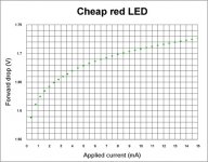
One more alternative is the use of diodes or LEDs to provide cathode bias voltage.
As for the cathode bias resistor, there are two ways to calculate it. You can do it with load lines (explained in any basic tube text like Terman or Seely), or do it iteratively, remembering to subtract the cathode voltage from the plate voltage for situation where the plate voltage is unusually low. For "normal" ranges of plate voltage, the shift because of cathode bias can be reasonably neglected, simplifying the calculation.
One more alternative is the use of diodes or LEDs to provide cathode bias voltage.
SY said:As for the cathode bias resistor, there are two ways to calculate it. You can do it with load lines (explained in any basic tube text like Terman or Seely), or do it iteratively, remembering to subtract the cathode voltage from the plate voltage for situation where the plate voltage is unusually low. For "normal" ranges of plate voltage, the shift because of cathode bias can be reasonably neglected, simplifying the calculation.
One more alternative is the use of diodes or LEDs to provide cathode bias voltage.
Thanks. I had a quick look through Seely but it doesn't seem to cover loadlines for the type of transfer curves given in the datasheet.
As for using diodes or LED's, I though they weren't recommended for bias currents less than 5-10 mA?
Thanks. What I am now thinking I will do is use some 4148's in series to bias the tube. That way I can adjust the amount of bias and try to get enough current to saturate the transformer for a dirty sound. I have a Edcor WSM10K/10K which I think will saturate somewhere in the 5-10 mA range, but I think I'll try to find some junk modem isolation transformers or junk ethernet pulse transformers, those should saturate with a much lower current.
As a practical matter, I haven't been able to measure the nonlinearity of LED biasing (my measurement capability is good to about 0.003% or so). If you want to be sure that the LED or diode is running more current, you can connect a resistor from the B+ to the cathode, sized to get the current you want.
") The pic is that transformer plus a 12EC8 and a Super 6BG6GA in the background
The pic is that transformer plus a 12EC8 and a Super 6BG6GA in the background 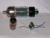
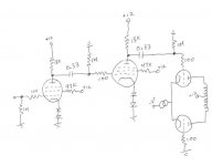
I'm still struggling with this. The single tube and tiny OPT didn't cut it, so I moved on to PP and the Edcor OPT. Levels are acceptable, but what is driving me crazy is that even with 2 pentode stages cascaded, I still can't drive the "output" stage into clipping. I have attached the schematic in case someone can point out the mistake. Right now I am thinking it is either because the 1M resistors on the grids on the 2nd pentode and output triode are way too big, or because I don't have a bypass cap on g2. Help?
Attachments
- Status
- This old topic is closed. If you want to reopen this topic, contact a moderator using the "Report Post" button.
- Home
- Amplifiers
- Tubes / Valves
- How to get cathode bias info from grid bias info?