I have a Fisher X-100A that is in the original form. I plan to to replace the old parts even though it is still very quiet with no audible hum from 2 feet away.
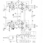
According to the (attached) service manual, the cathode of the EL84's are bias at -12V - 18V at the grid and 30V at the cathode. It is using a combination of a string of heaters (of 2 12AX7) + 22R resistor in series and parallel to a 2.2K resistor to ground. I am wonder:
1. why the cathode is at 30V but not higher,, 3 x 12AX7 in series is already at 12.6*3 = 37.8!! and these is a 22R resistor in the string. Maybe the grids are drawing some current??
2. Let say the cathode is indeed at 30V, then the 2.2K resistor at the top is drawing 13.6ma, and the heater should be drawing 150ma which implies the 4 EL84 are drawing around 40ma each. Correct? Looking at this tiny PT, I have serious doubt it can supply this much current. So, what am I missing here?
I know this is kind of dumb questions, but I just couldn't quite figure out how those voltages are derived with my minimal knowledge.
Thanks,
Attachments
 Hi, l shouldnt but in here, as l am not nearly knowledgeable to answer your questions, only l have one of these too, but mine originally came with 7189 tubes[ a higher rated version of the el 84 which mine are equipped with as 7189's are very rare and if you can find them are worth an arm and a leg, though there are some russian versions about, at much more reasonable prices] having said that; l upgraded some of the components with minimal sonic differences, caps mainly, so my advice is if you have nothing major wrong with your amp, leave it alone and enjoy it as it is....
 cheers T.C.
I do have a quad of NOS RCA 7189, but for now, it is cheap Sovtek time My amp is still amazingly quiet but doesn't sound as nice the Eico HF-81. My questions are kind of for my learning to understand how this cathode bias work. Since I have a 12.6VAC around, I can mount it to the chassis and run all 12AX7 off this little toroid, but then I will need to know what to put at the cathode of the output tubes
My amp is still amazingly quiet but doesn't sound as nice the Eico HF-81. My questions are kind of for my learning to understand how this cathode bias work. Since I have a 12.6VAC around, I can mount it to the chassis and run all 12AX7 off this little toroid, but then I will need to know what to put at the cathode of the output tubes Yes, it is true the eico's by all accounts were a sweet sounding amp. this all comes down to sonic signatures of the various components used in the original design; o/p transformers etc, sorry l cant be more specific, though l think your sovteks are as good as anything, l wouldnt worry about putting in the 7189's as you may not notice a real big difference, though it may not hurt to try 'em out.... as for the rest of your questions it wouldnt hurt to ask them on the vintage page of audio asylum there may be more knowledgable people there to answer your questions......... good luck and cheers T.C.
should've waited for you to post a reply, but l was chewing over this all morning when l realised what is causing such a sonic difference between the amps, when it occured to me that if my memory serves me right, the eico o/p transformer has an ul tap, so the output tubes are connected in ultra linear mode, wheras the fisher hasnt, the other thing you can try to sweeten the fisher up is to connect the op tubes in triode mode, [with a slight loss of power] if that doesnt make you happy you can try a svetlana sv83 tube in place of the 6bq5's which are similar [ AND ACCORDING TO REPORTS NICE SOUNDING TUBE oooops sorry didnt mean to shout], only the pins are configured differently, so a little rewiring will be necessary............ there now l got it off my chest, and mind, l racked my brains for that tubes number[ the sv 83 that is] cheers T.C.
 ps; decware builds and sells amps made with this tube, and as far as l can ascertain you should be able to get them from triode electronics................ all the best and good luck
The Eico HF-81 is also pentode only, no UL tap. It is based on Williamson design as well but uses tube rectification instead of SS diodes. I think the difference in the OT and the preamp section probably the major reason to explain the tonal difference. Quite frankly, which one sounds better is a personal opinion, not a universal one BTW, I also have a Fisher 400 receiver, but I haven't decided whether I shall gut the irons or restore it - the 7868 tubes are a little hard to get by these days, and I don't really need to FM section .....
BTW, I also have a Fisher 400 receiver, but I haven't decided whether I shall gut the irons or restore it - the 7868 tubes are a little hard to get by these days, and I don't really need to FM section ..... Fred, yes there is something to say for tube rectification, according to lore l have seen on the net this could account for the sonic differences that you have noticed, those that build their own from scratch would not consider anything else......... l remember reading in "sound practices" that l used to subscribe to; so l guess that explains it, should'ave thought of it and asked...... lucky guy having a 400, l have never seen one, doubt if any made it down here.............
cheers T.C.
Fred,
Don't get too hung up on the figures on the schematic.
These figures reflect that they are running the heaters of the V1 V2 and V3 low, => at 9V instead of 12V.
That was to get the current down a bit. Ideal current in that heater string (for a full 12V across each heater) is 150mA as you stated. That would infer an idle current of 150/4 = 37.5 mA per output tube. With an anode voltage of 390V that is 14.6 Watts dissipation which is over the rating of these tubes.
So what they have done is drop the current down. The effective bias is set by the voltage drop across V3 heater and the 22 Ohm resistor (adjust that 22 Ohm to get bias currents right).
A bit of back calculation suggests 3V across the 22 Ohm => 136mA or 34mA per tube. That is still running the output tubes pretty hard and a matched set of output tubes would be essential.
They have accepted the compromise of preamp tube heaters running low to get output tube dissipation down a bit. Of-course anyone designing this today and posting it for discussion would get an absolute caning. This is design "down to a price" and not "up to a standard" at its worst. There was a whole rash of amps which came out around the same time where the designers thought they were being "Clever" to use preamp heaters as cathode bias resistors in the power tubes. It gave a "free" heater supply so the power tranny could be smaller and cheaper and the amp could be $2 cheaper.
You know the old expression "He was so sharp its a wonder he did'nt cut himself". Well suffice to say that at the time there were some Hari-Kari types about designing amplifiers or at least one's who should have but did'nt, tell the accountant to "take a hike" (preferably off something tall).
On the positive side I guess I do need to conceed that they saved a whole 5 watts of power and heat.
I even once saw someone sketch up an amp design where he was going to use the output tube heaters themselves as their own cathode bias resistors. Boy did I have a laugh, no heater means no current means no heater etc. - you get the drift.
Cheers,
Ian
Fred,
I have to admit I don't know.
I looked at it to see if it was giving some protection in case of an open circuit heater (or pulled tube) on V1, V2 or V3 but it does'nt provide that.
Only thing it does do is keep the output stage "ticking" at very low idle currents if the above occurs and stops the cathodes from "floating".
Unless I'm missing something obvious I don't think it does anything except add about 3 and a bit mA per output tube.
Anyone else have a clue?
Cheers,
Ian
Thanks for your quick reply,Ian.
While I was taking a shower, I kept thinking what that resistor was for and arrived the same conclusion as yours - it is for keeping a ground path for cathodes if one of the filaments is open. Don't laugh, the shower seems to be a good place to think puzzles
While I was taking a shower, I kept thinking what that resistor was for and arrived the same conclusion as yours - it is for keeping a ground path for cathodes if one of the filaments is open. Don't laugh, the shower seems to be a good place to think puzzles
Hi I have a Fisher x-100-A that i restore,
I checked the voltage of the double voltage are as follow with tubes.What can I do?
replace the cap.with same value
39V at Pin3 = Cathode Pin
447V at Pin9 = Screen Grid Pin (340V)
484V at Pin7 = Anode/Plate (390V)
418v at point A (330V)
400v at point B (310V)
280v at point c (170V)
Thank you
I checked the voltage of the double voltage are as follow with tubes.What can I do?
replace the cap.with same value
39V at Pin3 = Cathode Pin
447V at Pin9 = Screen Grid Pin (340V)
484V at Pin7 = Anode/Plate (390V)
418v at point A (330V)
400v at point B (310V)
280v at point c (170V)
Thank you
Fred --
There's a couple of things at play here:
1. Fisher notoriously ran their preamp heaters at lower than spec voltage -- even when they used a true dc supply to power them, because operating the heater of small signal tubes under voltage spec in that kind of application results in lower noise from the tube. Radiotron and other reference this fact, and it plays out in my own experiments as well. The reduced heater voltage has little impact on the actual gain these stages provide, so performance is basically not impacted at all, but noise is reduced.
2. There is a very non-linear relationship of Ohm's Law as it relates to heater current draw, versus operating voltage. In your original post, you suggest that the heaters are drawing 150 ma, which at the reduced voltage they are operating at, they are not. Cold heaters draw the most current (hence the surge at turn on), but quickly fall to rated current at rated voltage as the tube heats. Operating the tubes "colder" (as Fisher is doing) does theoretically decrease their resistance which tends to increase current draw, but there is also less voltage across that resistance, so that current is ultimately lower than rated current flow. This has upset your assessment of plate dissipation and made it inaccurate.
The only way to get a true assessment is to measure the voltage across the 22 ohm resistor as it's value remains constant regardless of the resistance of the actual heater string. Calculate your current flow through that resistor, and then add to that the current flow through the 2.2K resistor. That will give you an accurate measurement of current flow then from the four tubes.
In relating this to plate dissipation, divide the total current draw by 4 to get the current draw per tube, and then subtract about 2 ma from the per tube figure to account for the screen current. What is left will be the actual plate current. Take this real plate current times 360 vdc (the actual plate voltage potential across the tube) to determine the real plate dissipation for each tube (if they are matched). I think you will find that the dissipation level of the tubes is pretty safe.
As for sound, the biggest difference between the Fisher and the Eico will be due to the line/tone amp stages. While I couldn't see that portion of your schematic, Fisher almost always used passive tone controls in these type amplifiers, while the Eico uses active feedback type tone controls which are far superior. They are always more accurate with excellent on center peformance (very flat), and as a result, will almost always sound much better than passive controls.
Good luck with your amp!
Dave
Hi Dave,
Thanks for your explanation as in the usual Dave way Yup, this is the same Fred who bothered you awhile ago. I still have the notes when I took the measurements, there was 2.97V across the 22R and voltage of pins 4-5 of the 12AX7 were 8.72, 8.98, and 9.09. So, it was biased to a little below 30V, approx. 135ma. The 2.2K draws approx 13.5ma. I think that's how I arrived 150ma. I also read that the heater voltage are perfectly fine within +/- 5% of the rated voltage, but this is more than 25% below, that's why I was puzzling.
Iswind,
I will choose the caps at the same voltage rating as the minimum and prefer to go for 350VDC rating vs the 250V per Fisher's part list. There is plenty of space underneath. You can easy fit 2 radial 100uF/350VDC caps there.
Thanks for your explanation as in the usual Dave way
Yup, this is the same Fred who bothered you awhile ago. I still have the notes when I took the measurements, there was 2.97V across the 22R and voltage of pins 4-5 of the 12AX7 were 8.72, 8.98, and 9.09. So, it was biased to a little below 30V, approx. 135ma. The 2.2K draws approx 13.5ma. I think that's how I arrived 150ma. I also read that the heater voltage are perfectly fine within +/- 5% of the rated voltage, but this is more than 25% below, that's why I was puzzling.Iswind,
I will choose the caps at the same voltage rating as the minimum and prefer to go for 350VDC rating vs the 250V per Fisher's part list. There is plenty of space underneath. You can easy fit 2 radial 100uF/350VDC caps there.
Lowered heater voltage DOES give reduced noise and increased life (at the expense of some gain). Not a bad trade in a low-level preamp - many designers used reduced heater voltage on the first few tubes. I think they set the heater voltage they wanted, then bumped up the idle current a few ma with the shunt resistor.
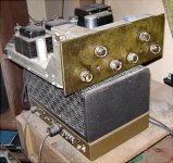
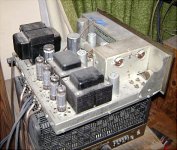
Here's some pictures of my Fisher X-101 on top of a Heathkit W-5M. I disconnected the preamp filaments from the cathodes of the EL84s and put in some cathode resistors in place of the filaments. I'd have to open it up to see exactly what I did. I've got some wires and a connector coming up through the top so I can measure the voltage at the cathodes to see if the EL84s are biased properly. I used the information in the RCA receiving tube manual to figure out the cathode current and voltage. I just found my bag of 330 ohm 5 W resistors, so IIRC, I put in one 330 ohm cathode resistor in each channel. The resistor is shared by both cathodes. I don't remember if I used a bypass capacitor or not.
Attachments
Last edited:
Someone gave me the X-101 for free in 1989. He said it didn't work and one thing I found wrong with it is that one of the 12ax7 preamp tube filaments was burned out. I had to replace a filter capacitor, too, which tended to get hot when the amp was on. I didn't think this type of arrangement would provide a very stable biasing arrangement so I disconnected the filaments and substituted a resistor bypassed with a capacitor. After some calculations I tried using a 9 hundred something ohm resistor (years ago) bypassed with an electrolytic capacitor. More recently I used 330 ohm cathode resistors in each channel (one 330 ohm per channel). It sounds similar to stereo amps that use 7591 output tubes, but the EL84 amps have less power. I read something years ago in Glass Audio Magazine about a shortage of 7591 tubes and this made me more interested in getting the X-101 fixed. There doesn't seem to be a shortage of 7591 tubes now, however.
Last edited:
- Status
- This old topic is closed. If you want to reopen this topic, contact a moderator using the "Report Post" button.
- Home
- Amplifiers
- Tubes / Valves
- How to figure out the bias point of fisher X-100A