I intend to use 807 beam tetrodes in a push-pull circuit triode connected with B+ 425V. The data sheet specifies Vg2 < 300V and Pg2 < 3W. I am afraid of reduced lifetime of the tubes when Vg2 is at the anode voltage 425V DC and peak AC voltage approaches 600V. I use 47 ohms resistors at g2. Do I need to worry about the Vg2 limitation? Could be reduced lifetime the consequence of elevating Vg2? If it is, how can I extend the lifetime of the tubes? Could it help increasing the g2 resistor, or would the triode characteristics be affected then? A series of Zener diodes could drop some 250V, but I am afraid it would destroy the good triode sound.
Thanks for any insight.
Thanks for any insight.
Yes, I would worry about screen grid limitations and reduced life. I grew up them... my Dad's amp used them... +550V on the plates, +275 on the screens with fixed bias... great sounding amp but even then it could toast them over time.... lotsa blue then eventually red plates. We were able to buy NOS JAN surplus 807s back in the late 60's and 70's for about $1 each... so no big deal. Nowadays... not so cheap. You might want to consider some NOS 6L6GC in triode mode.... most of the older tube manuals show triode-connected plate curve charts for them.
Regards, KM
Regards, KM
Patrick Turner has some things to say on this topic at the rec.audio newsgroup.
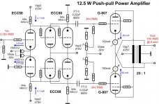
Thanks for the info. I made up that Vg2 may be tied to the anode if B+ is less than 450V (triode or UL). I built and use the attached circuit. The problem is that the grid bias needs frequently re-adjusted and the tubes have to be frequently replaced. I replace them when setting 30-50 mA bias current is not possible any more within -30V ... -50V Vg1 range. Could it be because of rapid tube aging due to over-spec Vg2?
Attachments
Yes, at 450 volts you are certainly stressing the screens and causing premature failure. There are some triode-connected specs located here:
http://tdsl.duncanamps.com/show.php?des=807
I suggest you more closely following the recommended ratings, and note that these are closer to maximum and should be toned down if you expect longer life. Good luck.
Regards, KM
http://tdsl.duncanamps.com/show.php?des=807
I suggest you more closely following the recommended ratings, and note that these are closer to maximum and should be toned down if you expect longer life. Good luck.
Regards, KM
If you're designing with 807s, you'll need the STC 807 Application Report. Includes information for triode operation. Operating at Vpp= 425V is a bit much for trioded operation.
Hi oshifis,Thanks for the info. I made up that Vg2 may be tied to the anode if B+ is less than 450V (triode or UL). I built and use the attached circuit. The problem is that the grid bias needs frequently re-adjusted and the tubes have to be frequently replaced. I replace them when setting 30-50 mA bias current is not possible any more within -30V ... -50V Vg1 range. Could it be because of rapid tube aging due to over-spec Vg2?
You ask me about two weeks ago if I can simulate your circuit on my SIMetrix simulator and it is done. This is a very nice amplifier design and it is very difficult to improve it.
I am glad about the results because that's a very good way to verify my 6DJ8 and 6L6GC Spice models, like I tell you before, the 6L6GC and 807 have very close caracteristics and I get very close results to what you schematic said
It is a really good idea to use the 1N5312 and 1N5313 diodes current limiter for the phase splitter current mirror but I don't have their Spice model so I just use the incorporated SIMetrix current source, it does exactly the same thing .
Here's your original circuit and results :
An externally hosted image should be here but it was not working when we last tested it.
The first thing I notice is your 6DJ8 drivers are in great danger ...
An externally hosted image should be here but it was not working when we last tested it.
This is something you should take care of as soon as possible because I know the 6DJ8 are very expensives ... The phase splitter tubes operation point look very good to me so I draw a corrected version with a close operation point for the driver too and a safe Va under 130V ... Not 269,5V ...

An externally hosted image should be here but it was not working when we last tested it.
Like you can see, you just have to change the 33K cathode resistors for 18K (R12 and R13) and add two 4,7K 2W (or more) resistor (R23 and R24) and a 47uF filter capacitor (C3) to get a 268,8V supply for the driver tubes. There is just a little bit more distortion this way but nobody will notice any differences for sure ...
This is a "pure class A" amplifier and just like a "class AB1", there is no current pull by the power tubes grids, so those four drivers tubes are not really needed :
An externally hosted image should be here but it was not working when we last tested it.
Of course, the distortion is a little bit higher but it is so simple ... However, there is a simple way to improve it, since you already use a current mirror for the splitter cathodes, why not use adjustable ones for their plates, using a good "TO220 high voltage DN2540 power depletion MOSFET" as current limiter ...
It improve the distortion and the gain ... It is still very simple and cheap, a DN2540 cost about 2,50$ and last for life but each time you replace your four 6DJ8 drivers, it cost you over 100$, think about it ... A phase splitter like that just need a 200V supply or a little more if necessary so you can get a better filtered supply for this stage. I left a 48V "headroom" for a signal up to 34V RMS plus 15,8V for the DN2540 Vds, it is plenty enough, just provide a very small heatsink for each of them will help if they get too hot.
An externally hosted image should be here but it was not working when we last tested it.
About using thoses MOSFET with the "corrected" circuit version :
An externally hosted image should be here but it was not working when we last tested it.
Now, you get a "Deluxe" version with safe operation point for the drivers and a distortion as low as the "original version" ...
About your 807 "longevity problem", there is not much to do for that because it is a fixed bias amplifier and this is hard for any tubes, the best is using a cathode bias circuit to protect the tubes ...
It is possible to make a circuit half way between fixed bias and cathode bias just by inserting small value resistors in the cathode circuit and use a corresponding lower fixed bias. Maybe it will help the 807 to live longer and produce less distortion but there will probably be a small lost of power ... I will make a simulation test about that this week.
Alain.

Last edited:
Hi oshifis,
I made some modifications to the version 6 and it did improve performances a lot ...
But first, I have to tell you something :
Since your drivers plate to cathode voltage is more than twice the 6DJ8 design center maximum, arcing between the plate and cathode can occur very often and since it is a cathode follower circuit, those arcs will produce some 415V positive peaks on the 807 grids and that is very bad for them ... Maybe, this is why they don't last very long ...
Yesterday, I tell you it is possible to make a circuit "partially fixed bias and partially cathode bias" and it work very well with just a little 5V cathode bias without too much power loss :
I notice in my tests the lower frequency response was not very good, it was not because the transformer but just because your 220nF coupling capacitors ... This is much too low for the following grid leak 100k resistors ... So I change them for some 2,2uF capacitors and it make a very big difference, but this is a minimum, you can use some larger ones, up to 4,7uf is OK, over that is useless.
I also add a "ficticious" serial 60K resistance at the input to represent the "ideal" source output impedance for this circuit, it is important for a good the high frequency response. Notice the 85 ohms resistors at the transformer (R2 and R3) are also "ficticious", they represent the DCR of the transformer primary ... Those resistors are not really in the circuit, it is just for the Spice simulation ...
Like you can read on the schematic, the maximum power is now slightly lower at 11,336W but the distortion at 1Khz drop to 0,740275% ... This is really good ... The frequency response is now vitually "flat" from 2,5Hz to 20Khz, within 0,135dB ... This is fantastic ... But to get this bass response, you need big 2200uF bypass capacitors across the 100 ohms cathode bias resistors ...
In a push-pull circuit, the maximum power is limited by the maximum voltage swing on the grids before the 0V clipping occur. The positive swing on the grid can reach this clipping but the operating class is define by the negative swing, when it don't reach the tube "cutoff" where the current is 0ma, the amplifier operate in class "A". If it cross this limit, it operate in class "AB1", the power is then greater but the distortion is usually higher ...
You told me in your message you dont like to use any bypass capacitors but like I told you, if you don't use them, distortion will reach about 3,5% at 1Khz and the power will be much lower. But it is possible to use a LED bias instead and higher bias and current for the 807 tubes, up to 60ma for a 25W plate dissipation.
This will be my next test, maybe for tomorrow is I am not to much busy.
Alain.
I made some modifications to the version 6 and it did improve performances a lot ...
But first, I have to tell you something :
Since your drivers plate to cathode voltage is more than twice the 6DJ8 design center maximum, arcing between the plate and cathode can occur very often and since it is a cathode follower circuit, those arcs will produce some 415V positive peaks on the 807 grids and that is very bad for them ... Maybe, this is why they don't last very long ...
Yesterday, I tell you it is possible to make a circuit "partially fixed bias and partially cathode bias" and it work very well with just a little 5V cathode bias without too much power loss :
An externally hosted image should be here but it was not working when we last tested it.
I notice in my tests the lower frequency response was not very good, it was not because the transformer but just because your 220nF coupling capacitors ... This is much too low for the following grid leak 100k resistors ... So I change them for some 2,2uF capacitors and it make a very big difference, but this is a minimum, you can use some larger ones, up to 4,7uf is OK, over that is useless.
I also add a "ficticious" serial 60K resistance at the input to represent the "ideal" source output impedance for this circuit, it is important for a good the high frequency response. Notice the 85 ohms resistors at the transformer (R2 and R3) are also "ficticious", they represent the DCR of the transformer primary ... Those resistors are not really in the circuit, it is just for the Spice simulation ...
Like you can read on the schematic, the maximum power is now slightly lower at 11,336W but the distortion at 1Khz drop to 0,740275% ... This is really good ... The frequency response is now vitually "flat" from 2,5Hz to 20Khz, within 0,135dB ... This is fantastic ... But to get this bass response, you need big 2200uF bypass capacitors across the 100 ohms cathode bias resistors ...
In a push-pull circuit, the maximum power is limited by the maximum voltage swing on the grids before the 0V clipping occur. The positive swing on the grid can reach this clipping but the operating class is define by the negative swing, when it don't reach the tube "cutoff" where the current is 0ma, the amplifier operate in class "A". If it cross this limit, it operate in class "AB1", the power is then greater but the distortion is usually higher ...
You told me in your message you dont like to use any bypass capacitors but like I told you, if you don't use them, distortion will reach about 3,5% at 1Khz and the power will be much lower. But it is possible to use a LED bias instead and higher bias and current for the 807 tubes, up to 60ma for a 25W plate dissipation.
This will be my next test, maybe for tomorrow is I am not to much busy.
Alain.
oshifis,
I just found out I was wrong about something ...
Your amplifier don't operate in class "A" but in class "AB1"
In fact, it operate in class "A" just below 2,73W ...
My mistake was I monitor the voltage at the plate of a 807 and I see a nice sinusoïdal because the push-pull transformer, it is the current I have to monitor !
Alain.
I just found out I was wrong about something ...
Your amplifier don't operate in class "A" but in class "AB1"
An externally hosted image should be here but it was not working when we last tested it.
In fact, it operate in class "A" just below 2,73W ...
My mistake was I monitor the voltage at the plate of a 807 and I see a nice sinusoïdal because the push-pull transformer, it is the current I have to monitor !
Alain.
oshifis,
You ask me in your message what is the difference between the same circuit with the "Quad style" connexion and the "usual" connexion like with a standard transformer :
Much less input voltage is needed to reach the maximum power. The output power is slightly lower but the distortion is slightly higher except at 20Khz because there is more power loss at that frequency ...
Alain.
You ask me in your message what is the difference between the same circuit with the "Quad style" connexion and the "usual" connexion like with a standard transformer :
An externally hosted image should be here but it was not working when we last tested it.
Much less input voltage is needed to reach the maximum power. The output power is slightly lower but the distortion is slightly higher except at 20Khz because there is more power loss at that frequency ...
Alain.
Just curious about a couple points:
1. Why parallel the cathode followers? The source Z of a single 6DJ8 CF is low enough to put the HF pole more than a decade higher than the transformer rolloff.
2. Why direct couple the CF to the driver stage and cap couple to the output stage? If you do it the other way around, you can have saner voltages on the 6DJ8 and make the amp much more resistant to blocking.
Alain,oshifis,
You ask me in your message what is the difference between the same circuit with the "Quad style" connexion and the "usual" connexion like with a standard transformer :
An externally hosted image should be here but it was not working when we last tested it.
Much less input voltage is needed to reach the maximum power. The output power is slightly lower but the distortion is slightly higher except at 20Khz because there is more power loss at that frequency ...
Alain.
Thanks for your efforts and the analysis. I will follow your advices and modify the circuit in the following order:
1. Decrease the plate voltage of the cathode follower. Fortunately, I just need to replace a single resistor in the power supply.
2. Put some LEDs in the cathode to get about 5 to 10 V cathode voltage. What type of LED is most suitable for this (green, red, high-efficiency, ...)?
3. Increase the grid resistor of the output tubes to 220K and/or increase the coupling capacitor (but I don't easily replace those nice Russian teflon capacitors...)
I will report on the results, may take some time until I implement them.
Here are some pictures of the amplifier:
https://picasaweb.google.com/lcsaszar/807_amplifier
Only oshifis can answer those questions because he build the amplifier that way ...Just curious about a couple points:
1. Why parallel the cathode followers? The source Z of a single 6DJ8 CF is low enough to put the HF pole more than a decade higher than the transformer rolloff.
2. Why direct couple the CF to the driver stage and cap couple to the output stage? If you do it the other way around, you can have saner voltages on the 6DJ8 and make the amp much more resistant to blocking.
He ask me to help him find some ways to improve it and this is what I am doing. But I don't think he like to modify it too much ... Just some few adjustments ...
Only oshifis can answer those questions because he build the amplifier that way ...
I thought it was your design, and was going to ask the same couple of questions, by the way.
Alain,
Thanks for your efforts and the analysis. I will follow your advices and modify the circuit in the following order:
1. Decrease the plate voltage of the cathode follower. Fortunately, I just need to replace a single resistor in the power supply.
2. Put some LEDs in the cathode to get about 5 to 10 V cathode voltage. What type of LED is most suitable for this (green, red, high-efficiency, ...)?
3. Increase the grid resistor of the output tubes to 220K and/or increase the coupling capacitor (but I don't easily replace those nice Russian teflon capacitors...)
I will report on the results, may take some time until I implement them.
Here are some pictures of the amplifier:
https://picasaweb.google.com/lcsaszar/807_amplifier
Congratulation Laszlo, your amplifier is very nice !
An externally hosted image should be here but it was not working when we last tested it.
Tonight, I made five more tests and I find the best you can do to improve it without doing too much modifications like you will see in my two next posts !
About your comments :
It was not a very good idea to use a LED bias for this circuit, the distortion would be too high ...
You cannot use a higher value grid leak resistor in a fixed bias circuit for the 807 ... The maximum is 100K, it is written in every 807 datasheets ... You will have to replace the 220nF with some good paper or film 2,2uF capacitors to get the optimum frequency response and the lower distortion ...
Alain.
I will show my five tests results now.
But first, the two horrors ...
The results with a partial LED bias ...
When I see the 2,48% distortion at full power, I stop this test right there ...
Just for fun, I verify what results a "cathode bias only" would give :
Ouch ! Over 7% distortion ... really horrible ...
No more comments about thoses two !
But first, the two horrors ...
The results with a partial LED bias ...
An externally hosted image should be here but it was not working when we last tested it.
When I see the 2,48% distortion at full power, I stop this test right there ...
Just for fun, I verify what results a "cathode bias only" would give :
An externally hosted image should be here but it was not working when we last tested it.
Ouch ! Over 7% distortion ... really horrible ...
No more comments about thoses two !
Now, the good stuff !
I replace the 220nF coupling capacitors of the "version 2" with some 2,2uF and I redo the tests and there is a big difference. The maximum power is higher and the distortion at this power is much lower and the bass response is fantastic but unfortunately, the distorsion raise when the power is lower ...This is a strange thing some tubes do in push-pull because their "non-linarity" and the "operating point" chosen ...
I call it V2A and I start from for the two last ones.
There is no ways to really increase the maximum power without using a lower load impedance, the 807 datasheets typical operations for push-pull with triode connexion said 15W can be reach with a 3k plate to plate load ... With a 5K load at this supply voltage, it is impossible to go much over 12W without "clipping distorsion" ...
I make a first test with a lower cathode current to see the effects of going deeper in class "AB1" ...
Like you can see, with a 40ma cathode current, the maximum power is a little bit lower than with the V2A but at this power, the distortion is much lower, only 1,19% at 1Khz ... The problem is : The distortion raise to 1,57% at 9,376W and 2% at 6,34W and stay high at lower power ... I don't think that is what you want ...
So, I figure out it is better to go deeper in class "A" instead by raising the cathode current ... The 807 datasheets said the combined plate and screen grid dissipation should not exceed 25W in "constant service" (CCS) but since the dissipation in "intermittent service" (ICAS) is 30W maximum, it cannot hurt the tubes if it is slightly more than 25W ...
So the current can be raise to 60ma because the supply is 419,9V and 419,9 x 0,06 = 25,194W ...
This is the circuit that give the higher maximum power, 12,818W ... Yes, at this power, the distortion is higher, 1,952%, but lower at 20Khz ... But what is very interresting with this circuit is : The distortion drop a lot at lower power, 1,67677% at 6,7667W and only 0,525741% at 3,5666W ... A very "normal" listening power with high efficiency loudspeakers ...
I think that is what you want !
So all what you have to do to improve your superb amplifier is :
1 - Lower the drivers supply to about 268,8V to protect them and the 807 ...
2 - Change your 220nF coupling capacitors for some good 2,2uF to 4,7uF
3 - Adjust the 807 cathodes current to 60ma ( but no more ... )
And like we said in Quebec : "Everything will be tigidou"
I will verify what is the distorsion of the "V2C" at 1W, 20Hz, 1Khz and 20Khz and tell you in my next post later. That is about the power I play my "vinyls" home not to disturb all the close neighbours ...
Alain.
I replace the 220nF coupling capacitors of the "version 2" with some 2,2uF and I redo the tests and there is a big difference. The maximum power is higher and the distortion at this power is much lower and the bass response is fantastic but unfortunately, the distorsion raise when the power is lower ...This is a strange thing some tubes do in push-pull because their "non-linarity" and the "operating point" chosen ...
I call it V2A and I start from for the two last ones.
An externally hosted image should be here but it was not working when we last tested it.
There is no ways to really increase the maximum power without using a lower load impedance, the 807 datasheets typical operations for push-pull with triode connexion said 15W can be reach with a 3k plate to plate load ... With a 5K load at this supply voltage, it is impossible to go much over 12W without "clipping distorsion" ...
I make a first test with a lower cathode current to see the effects of going deeper in class "AB1" ...
An externally hosted image should be here but it was not working when we last tested it.
Like you can see, with a 40ma cathode current, the maximum power is a little bit lower than with the V2A but at this power, the distortion is much lower, only 1,19% at 1Khz ... The problem is : The distortion raise to 1,57% at 9,376W and 2% at 6,34W and stay high at lower power ... I don't think that is what you want ...
So, I figure out it is better to go deeper in class "A" instead by raising the cathode current ... The 807 datasheets said the combined plate and screen grid dissipation should not exceed 25W in "constant service" (CCS) but since the dissipation in "intermittent service" (ICAS) is 30W maximum, it cannot hurt the tubes if it is slightly more than 25W ...
So the current can be raise to 60ma because the supply is 419,9V and 419,9 x 0,06 = 25,194W ...
An externally hosted image should be here but it was not working when we last tested it.
This is the circuit that give the higher maximum power, 12,818W ... Yes, at this power, the distortion is higher, 1,952%, but lower at 20Khz ... But what is very interresting with this circuit is : The distortion drop a lot at lower power, 1,67677% at 6,7667W and only 0,525741% at 3,5666W ... A very "normal" listening power with high efficiency loudspeakers ...
I think that is what you want !
So all what you have to do to improve your superb amplifier is :
1 - Lower the drivers supply to about 268,8V to protect them and the 807 ...
2 - Change your 220nF coupling capacitors for some good 2,2uF to 4,7uF
3 - Adjust the 807 cathodes current to 60ma ( but no more ... )
And like we said in Quebec : "Everything will be tigidou"
I will verify what is the distorsion of the "V2C" at 1W, 20Hz, 1Khz and 20Khz and tell you in my next post later. That is about the power I play my "vinyls" home not to disturb all the close neighbours ...
Alain.
This is not my design but I am very interrested using some 807 for my personnal home sound system with the "vintage" Eico ST-40 output transformers I got. Because they are good low cost tubes ... Maybe I will use some 6CA7 or 6550 but I don't decide yet ...I thought it was your design, and was going to ask the same couple of questions, by the way.
Of course, I will make the best design I can for that amplifier and a complete tubes preamplifier with tone controls for my magnetic turntable and also a monophonic output with a mixer and a lowpass filter for my 50 pounds 12" chinese subwoofer.
My simulation tests with the 6S19P triode is only for a "DIY project" design to put on my personnal website I am working on some times. But I have to modify it all because it was only in french and I will do it french and english to join more peoples all over the world, it is a lot of work ...
What I am really doing on DiyAudio beside having fun and practice my "english writing" is "PR" ( public relation ).
Alain.
I just finish measuring the distortion and frequency response of the V2C circuit at 1W ...
Alain.
How about that ?OSHIFIS V2C with a 90H K=0,99992 OPT
Total distortion and frequency response at 1W :
1Hz : 0,310959% - 2,875200dB
2Hz : 0,298093% - 0,814134dB
5Hz : 0,293531% - 0,134640dB
10Hz : 0,293112% - 0,032711dB
20Hz : 0,292358% - 0,007070dB
50Hz : 0,282578% - 0,000050dB
100Hz : 0,292749% 0dB
200Hz : 0,293065% 0dB
500Hz : 0,288049% 0dB
1Khz : 0,279339% 0dB
2Khz : 0,229143% - 0,003730dB
5Khz : 0,276340% - 0,030750dB
10Khz : 0,261454% - 0,261454dB
20Khz : 0,161489% - 0,526526dB
50Khz : 0,209793% - 2,604000dB
100Khz : 0,178489% - 6,318200dB
Alain.
- Status
- This old topic is closed. If you want to reopen this topic, contact a moderator using the "Report Post" button.
- Home
- Amplifiers
- Tubes / Valves
- 807 Tube Triode Connected