Hi,
Is there any wisdom or guidance on spacing and orientation of transformers, to avoid crosstalk or mutual inductance issues?
I'm looking at mounting 4 impedance matching transformers in a common enclosure. Signal levels are low level, <10 Vrms. Wide spacing means a larger cabinet, which increases costs markedly.
I guess it depends on what type of transformers you're using. Assuming you're building a multichannel mixer, an inch (or more) appart should be reasonable for this low level. I once built a tube mixer using UTC A10 transformers that were about that close. But they are enclosed in a metal box as made, although not mu-metal. If your transformers are unshielded open frames, you could turn them 90º from each other as is done with larger higher level transformers to help prevent co-interference.
Victor
Victor
Transformers come in a wide variety of styles. I think that you have to look at the individual coils and frame and make a decision based on that. I would guess that you want to be orienting solenoidal axes orthogonally, or parallel in the same plane.
You might get some idea of the field shape with a small compass needle and some LVDC excitation.
Or you could actually do some testing by exciting one transformer and seeing what you can pick up on another in various orientations.
w
You might get some idea of the field shape with a small compass needle and some LVDC excitation.
Or you could actually do some testing by exciting one transformer and seeing what you can pick up on another in various orientations.
w
wakibaki said:Transformers come in a wide variety of styles.
These would be E-I laminations, such as made by Edcor. Thanks.
I suppose in a perfect world, you would arrange EI transformers so that no two sets of laminations are parallel to each other. Further, the central axis of the windings should not be parallel to each other.
I would try to line things up so that the center axis of the windings of one transformer is on the X axis (power), the second is on the Y axis (filter choke), and the third is on the Z axis (output or outputs). Again, spin them around their axis as need be to ensure that the laminations are perpendicular.
If the amp is a stereo unit, I will arrange the two output transformers in the same plane, or in parallel planes.
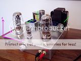
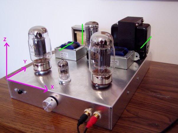
I spotted a photo of an amp (not one of mine) that illustrates a few of the concepts of transformer orientation. I've added some pink lines to depict the X, Y, Z axes and some green lines to show the direction of the axis of each transformer. I feel the open frame transformers make it a little easier to visualize the windings.
While the builder of this amp did arrange the transformers so that all the laminations are perpendicular to each other, he put the axis of the power transformer (big black one) in the same direction as the output transformers (little blue ones). In the photo, you can see they both point in the direction of the Y axis.
I might suggest turning the power transformer 90 degrees so that it points to the X axis. Of course, this would place the laminations of the power transformer in the same plane as the filter choke (tan colored). To remedy this, I would then turn the filter choke 90 degrees. I think this would make everything as "perfect" as it could possibly get.
Of course, in reality there is a bit of trial and error involved...
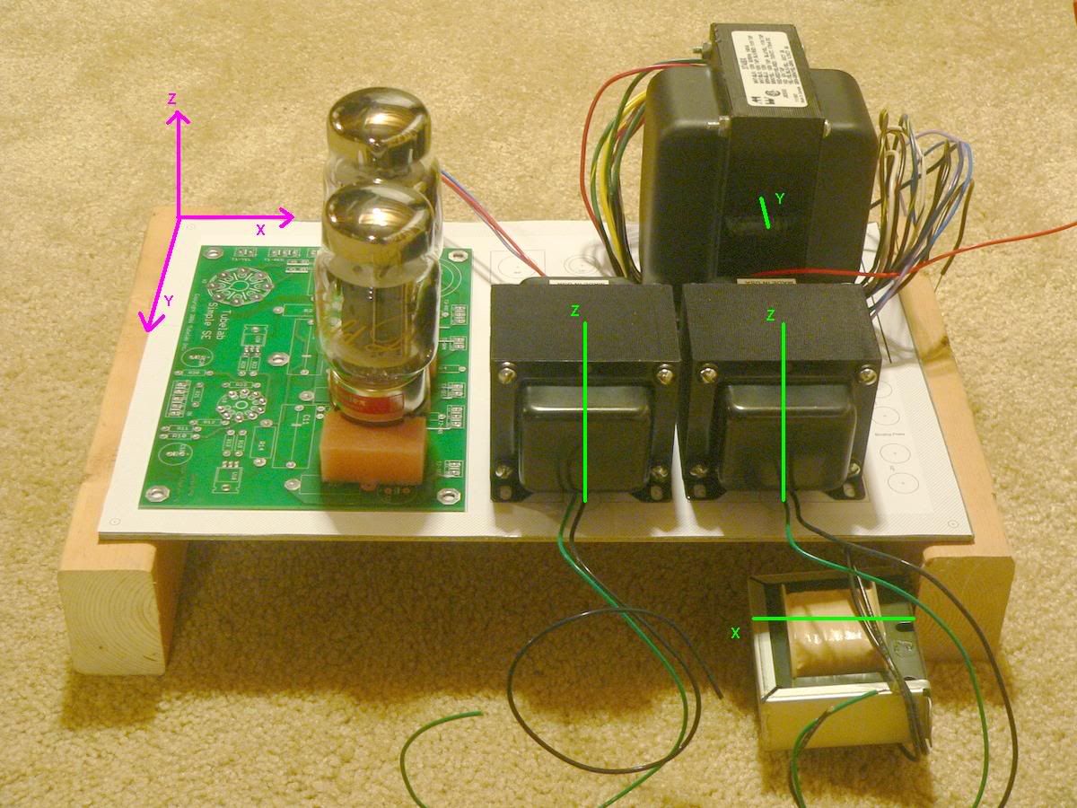
Here's another example. I'm planning to build this amp in the near future. I've got the transformers, and this photo shows how I intend to arrange them. The filter choke will be mounted under the chassis, probably screwed to the side of the frame. The power transformer has it's axis in the Y direction, the filter choke is in the X, and the output transformers are in the Z. Laminations are turned so that they are perpendicular to the others.
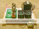
I haven't built it yet, but hopefully it won't hum.
I haven't built it yet, but hopefully it won't hum.
This is a box with 4 impedance matching transformers, I would orient them so that the 2nd and 4th are 90 degrees relative to the 1st and 3rd.. The field strength follows square law so for every doubling of distance between the transformers the field falls by half. Cross talk between the non adjacent pairs should not be much of an issue by virtue of their distance.
The above was the quick and dirty approach, if you are willing to do a bit more work you can drive one transformer and using headphones use another as the "pick up coil" - and determine what orientation produces the least coupling and mount these two that way. Now drive the transformer previously used as the "pick up coil" and use another as the "pick up coil" - and again orient and mount this one for minimum pick up, and repeat until done.
You can keep the box relatively small this way as well.
kevinkr said:This is a box with 4 impedance matching transformers, I would orient them so that the 2nd and 4th are 90 degrees relative to the 1st and 3rd.. The field strength follows square law so for every doubling of distance between the transformers the field falls by half. Cross talk between the non adjacent pairs should not be much of an issue by virtue of their distance.
You can keep the box relatively small this way as well.
Wow, a response from one of the masters....
This was helpful, and what I was looking for.
The tranformers are small Edcors, about 2" cube. If I hear you correctly, I can mount these in a row, and make sure that adjacent transformer cores are oriented perpendicular. The ones that would be oriented the same would be 6" center-to-center apart, if I allow 1" between cores. For small signals, this is probably adequate.
Thanks for the help!
- Status
- This old topic is closed. If you want to reopen this topic, contact a moderator using the "Report Post" button.
- Home
- Amplifiers
- Tubes / Valves
- Transformer spacing