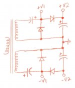
Could you please have a look at the attached schematic and let me know if this is the correct way to build a bipolar voltage doubler?
The application is a hybrid guitar amp, so the undoubled taps (+/- V1) are for the power opamp, and the doubled taps (+/- V2) are for the tube front end. TIA
The application is a hybrid guitar amp, so the undoubled taps (+/- V1) are for the power opamp, and the doubled taps (+/- V2) are for the tube front end. TIA
Attachments
LB,
That sure looks like a pair of Villard (1/2 wave) doublers wired up in opposite polarity to me. The ripple freq. is the mains freq.
With the same parts count, you can construct a pair of Greinacher ("full wave") doublers and get a 2X mains freq. ripple fundamental.
If you go Greinacher, put a single "high" current/low DCR choke between the rail common line and signal ground. Identical reservoir caps. get added to each rail. Notice that 1 choke serves both rails. Remember, PSUs are inherently differential. We make them single ended, bipolar, or what have you by where we connect the signal ground, AKA common return.
Steerpike said:V1 and -V1 will have a *very* large ripple content - probably way too large to be useable. Probably better to ignore the points V1, -V1 and use a separate pair of diodes and caps to get the undoubled DC.
Yup. After I posted this I tried to simulate in PSUD, and indeed the V1 points are unuseable for large currents. As for putting a doubler in parallel with a bridge on the same AC feed, won't they short each other out?
Tony said:hi,
why not just use a full wave voltage doubler? if you wanted +/- rails, you can have it with a full wave voltage doubler...
it makes things much simpler imho...
Doesn't a full wave voltage doubler have even more problems? If you are drawing 1A where the two caps connect to each other and 10 mA at the positive of the top cap doesn't the whole scheme fall apart?
hi,
in that case we have to see the schematics of the actual amp so we can have a more apprpriate comment...
voltage doublers are not know for good regulation, but considering that transformer utilization is very good, it is very hard not to use them in circuits where current draw is southwards of 1 amp...
Yup. After I posted this I tried to simulate in PSUD, and indeed the V1 points are unuseable for large currents.
LB,
Let's go back to square 1. I believe your objective is a PSU that yields +/- nV. and +/- 2nV. Pete Millett has shown how to extract 2 rails (1 low and 1 high) from a single, CT, rectifier winding, with both rails being truly full wave rectified.
You would have to construct a mirror pair of such supplies.Full wave bridge rectify the entire winding. That yields the high rail. Connect an additional diode to the CT of the rectifier winding. That yields the low rail. Yes, the low rail is truly full wave rectified. The diodes that form the connection to ground for the high rail also form the connection to ground for the low rail.
- Status
- This old topic is closed. If you want to reopen this topic, contact a moderator using the "Report Post" button.
- Home
- Amplifiers
- Tubes / Valves
- Correct for bipolar voltage doubler?