I'm planning some amps for a multi-way system with crossovers built in (via interstage coupling constants)
With the S&B TVC, we have a primary inductance of about 400H.
If I use a 5nF blocking cap and parallel a 200k res with the primary, then that gives me a 2nd order Butterworth rolloff at 110Hz which is where I want to crossover.
Elsewhere in the mid/treble amp, I could have an LC coupled stage, similar to the above. Voila, 4th order Linkwitz-Reilly (cascade of 2 2nd order Butterworths) with no additional circuitry (sort of).
I'd then need another attenuator for the bass with the same steps (could go for cheap resistive atten. as less critical).
This approach would keep LF from the TVC which is another benefit.
But my concern is that the 5nF cap, having such a high impedance, might make things sound weedy. Obviously I'd need a high i/p impedance valve right by the output of the TVC...
Anyone got any thoughts as to how well this approach might work?
Cheers
cv
CV said:Anyone got any thoughts as to how well this approach might work?
Not a clue I'm afraid, old boy.
However I thought that someone ought to respond....
")
7N7
MORALLY OBLIGED TO RESPOND...
Hi,
I know the feeling...
A hell of an expensive way to deal with filters I'd say.
If you ask me I'd use the things for what they were designed for if at all...
Cheers,
Hi,
However I thought that someone ought to respond....
I know the feeling...
A hell of an expensive way to deal with filters I'd say.
If you ask me I'd use the things for what they were designed for if at all...
Cheers,
Allo all,
Thanks to all who replied.
Well, it's a tricky one - I wasn't expecting too many replies as it's something that I've never seen suggested before; it's a bit at the fringe...
Frank - you're right, it's an expensive way of building a filter, but if the TVCs are already bought and paid for...
The main issues I can see are:
1) Following stage must have very high impedance
2) The inductance of the TVC is a function of frequency and level.
As regards (2), that's what air-gaps are for. Dunno how much of a gap S&B use though...
Now if we are filtering the audio signal -12db/octave at 120Hz, our ac flux on the core is much lower, which should reduce (already low) distortion, but I was thinking that this might give us some headroom to apply a tiny dc bias current to the primary (say a few microamps) which I was thinking might help linearise the inductance. I'm guessing the B-H curves are unlinear around zero crossing, so we'd get away from that. Much like gapped SE vs ungapped PP transformers.
Wish I had the test gear to check this out...
And don't forget, in addition to getting a filter for "free" it means we can use a lower value, higher quality cap.
Cheers
analog_sa said:Seems like there is no airgap. Which is of course a pity. Do you really need 400H? 40 would do me fine and i bet it would sound better too.
cheers
peter
Hi Peter,
I agree with you there; the TVC does have 2 primary windings which can be wired in parallel to give a quarter of the inductance - but it would be nicer to achieve 100H with a bigger air-gap...
The TVCs are on loan to a friend at the moment; when I get them back I'll see if Ican make some crude measurements of L vs level and frequency.
cheers
hey chris... thanks for the pointer
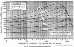
its interesting to note that looking at the curves in the old texts for perm vs frequency for various values of H (dc offset) that small amounts of H while reducing the perm, do make the perm much more linear, which seems to be a very similar behavior to what an airgap does.
dave
but I was thinking that this might give us some headroom to apply a tiny dc bias current to the primary (say a few microamps) which I was thinking might help linearise the inductance. I'm guessing the B-H curves are unlinear around zero crossing, so we'd get away from that. Much like gapped SE vs ungapped PP transformers.
its interesting to note that looking at the curves in the old texts for perm vs frequency for various values of H (dc offset) that small amounts of H while reducing the perm, do make the perm much more linear, which seems to be a very similar behavior to what an airgap does.
dave
Attachments

Hey Dave,
Welcome aboard - I think you'll feel at home here; good to have you around.
Ta very much for the graphs; just a few questions on interpretation.
1) For a given flux , is the mu just what you read off the line? Eg with 10 oersteds bias at 70 gauss the core perm is 70 * mu(vacuum) ?
2) Can't remember: seem to recall 1T = 10 kG, that right?
These really do reveal how inductance changes with level and frequency. Now I just need to see what they look like for mumetal for the airgap S&B are using...
Cheers,
Chris
CV said:1) For a given flux , is the mu just what you read off the line? Eg with 10 oersteds bias at 70 gauss the core perm is 70 * mu(vacuum) ?
[/B]
not sure i follow.... to me this graph says a small amount of dc decreases the incremental perm as expected, but it also linearizes the perm too....
actually the numbers are pretty much useless for anything but that archaic steel with the core configuration (lap joints)... but the relationship holds for most if not all current iron. in other words the shapes of the lines remain similar, but the scales change. (from what i gather)
it is interesting to note that these graphs were taken from the smallest possible airgap obtainable with stamped lams (equivalent of 1X1 stacking of EI's) oddly enough i see a similar behavior when you adjust the airgap of lams with stacking method.
dave
Attachments
Drat- just lost the reply... will repeat...
To clarify the interpretation of the first set of graphs; I got the numbers messed up, I meant if you take a flux of about 60-70 gauss (x-axis) and the 10 Oersted dc bias "loadline" - is it correct to then read that as the core having a relative perm of 200 (ie 200 * perm of air)?
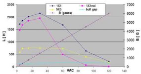
As for the 2nd, homegrown graph, v.v. nice! So much info in there.
The butt-gap (too many innuendos...) is truly a thing of beauty.
Even with the 5x5, if we apply a dc bias to take it to about 2000 gauss (equivalent to the flux of a 30vac signal) and are then sure to swing signal only within the area where the yellow line is flat (approx 800-2800 gauss) - we should have a pretty linear inductor.
If the S&Bs are indeed 5x5 or similar - my scheme may just work then; the -12db/oct rolloff at 120Hz may just buy enough headroom...
Thanks for the info - really does tell a 1000 words.
cheers
cv
To clarify the interpretation of the first set of graphs; I got the numbers messed up, I meant if you take a flux of about 60-70 gauss (x-axis) and the 10 Oersted dc bias "loadline" - is it correct to then read that as the core having a relative perm of 200 (ie 200 * perm of air)?
As for the 2nd, homegrown graph, v.v. nice! So much info in there.
The butt-gap (too many innuendos...) is truly a thing of beauty.
Even with the 5x5, if we apply a dc bias to take it to about 2000 gauss (equivalent to the flux of a 30vac signal) and are then sure to swing signal only within the area where the yellow line is flat (approx 800-2800 gauss) - we should have a pretty linear inductor.
If the S&Bs are indeed 5x5 or similar - my scheme may just work then; the -12db/oct rolloff at 120Hz may just buy enough headroom...
Thanks for the info - really does tell a 1000 words.
cheers
cv
- Status
- This old topic is closed. If you want to reopen this topic, contact a moderator using the "Report Post" button.
- Home
- Amplifiers
- Tubes / Valves
- Using TVC as a filter?