Hi all,
I am designing a pentode constant current sink based around the PCF80. I have a few options for operating conditions. I ideally want the current to be about 10mA. I will use Zeners to set g2 as I haven't got space for rc filtering the screen.
If I set the g2 voltage to 100V and have the plate at 100V I only have a g1 of -0.5V which will make for a not very stiff CCS.
Alternatively I can choose to set the g2 at 170V and have the plate at 100V which puts g1 at -2V. This should be a bit stiffer.
However if I set the g2 to higher than the plate then screen current is likely to be excessive. There are no figures for this so I would like to ask if anyone can give an estimate of g2 current if running the plate at 10mA and screen at 170V. I guestimated that it might be as much as 4mA which puts the g2 at 0.68W diss which is very close to its limit of 0.75W.
Has anyone out there built a CCSink with the PCF80, or has experience of screen current with a similar pentode.
That sounds usable. How did you derive that figure.
The standard tables suggest that with the a plate at 170V, g2 at 170V and g1 at -2V the screen current would be at about 3mA. Since the scenario I am proposing is worse than that your estimate of 3mA seems to be a bit conservative.
Shoog
The standard tables suggest that with the a plate at 170V, g2 at 170V and g1 at -2V the screen current would be at about 3mA. Since the scenario I am proposing is worse than that your estimate of 3mA seems to be a bit conservative.
Shoog
Hi Shoog
On page 108 of Valve amplifiers, 3rd edition, there is a schematic of a ECF80 based CCS. Mr. Jones uses 200V on the screen and 23V (through a voltage divider) on the grid, and finally a 2k cathode resistor. The resulting plate current should be 10mA, while the screen current should be 2,6mA*.
Erik
Shoog, have you solved your overshoot problems with the tabor clone?
*To moderators: if this copyrighted info can/may not be published here you are free to remove it.
Yves - Thanks for that. The graphs seem to suggest that I should be expecting a grid current of about 4mA which is in line with my guestimate. It certainly look workable.
Erik - that looks very promising, could you scan and send me the page. Theres no point in reinventing the wheel now.
The tabor clone is up and running and working amazingly well. Detailed punchy and sweet sounding. Best I have built so far. Still have a few issues with transformer saturation with 20hz signals, but I can live with that. The overshoot problem was mainly a problem with the CCS in the cathodes. They kept failing and overloading the powersupply. This was causing sever ringing between the output transformers and the power supply transformer. Once I got a robust enough CCS the ringing went away. I had to use TV deflection transistors in the end with a Darlington in a ring of two CCS. It surprising how easily you can stray outside the safe operating area on high voltage transistors in switch-on conditions. In those situations transistors become silicon fuses.
Shoog
I have just looked at the Morgan Jones example more carefully and it doesn't specify the anode voltage at all. The context it is described in suggests that the anode voltage is 100V. Still the design would seem to be only appropriate to a limited range of anode voltages. Maybe the g2 current isn't as variable with anode voltage as some texts would suggest. I assume that Morgan Jones built this CCS and used it in place of the 100V ECC88 CCS he describes on that page.
This gets to the nub of the issue - what exactly is the relationship between anode voltage and g2. Yves tables seem to suggest that beyond the knee of the g2 curve current for g2 is almost constant. If so then I'm getting myself into a state over nothing.
Shoog
This gets to the nub of the issue - what exactly is the relationship between anode voltage and g2. Yves tables seem to suggest that beyond the knee of the g2 curve current for g2 is almost constant. If so then I'm getting myself into a state over nothing.
Shoog
If so then I'm getting myself into a state over nothing.
Yes, you are.
The anode voltage is indeed non-critical because the plate resistance is so high (i.e., the ip vs ep curves are quite horizontal, especially when degenerated). Screen current is a separate issue, but it is (as Yves says) pretty constant unless you operate the screens at very low voltages.
Thanks for that SY.
I assume that g3 prevents g2 from becoming the dominant element in current flow through the pentode. So in tetrodes g2 current would be much more dependent on its relationship to anode voltage and so the issues I was concerned about would be relevant. With a true pentode these issues have been "solved".
Shoog
The cathode current, that is the sum of screen and pate ones, is almost constant whatever the plate voltage applied, funny isn't ?
So, if used as a plate load for another tube, a penthode is a very good CCS providing that the Vsk voltage remains constant.
I insist: Vs relative to Vk, not to ground ! That is the problem !
Easiest to say than to do !
If you put a zener between screen and cathode, then you introduce another variable : the zener current itself.
At least, screen should be by passed to the cathode.
Silly and unchecked idea: use the remaining triode as a cathode follower to "clamp" the Vs voltage to the Vk one
Uesd as a cathode load, just the plate current matters and as long as plate voltage remains "above the knee", the situation may be somewhat simpler !
Yves.
Hi SY,
Duh ? You mean "the plate at very lo voltage" . . . I guess ?
Yves. (Back in Ardeche)
SY said:
. . . unless you operate the screens at very low voltages.
Duh ? You mean "the plate at very lo voltage" . . . I guess ?
Yves. (Back in Ardeche)
Look at this quote from the Valve Wizard site;
This is where my confusion came from.
The full reference can be found at
http://www.freewebs.com/valvewizard/pentode.html
Shoog
It should be noted that if the screen grid were to be connected to a higher voltage than the anode, then anode current would drop rapidly while screen current would rise rapidly or 'runnaway' (it would be acting as the primary anode), and will quickly exceed its maximum ratings and be destroyed.
This is where my confusion came from.
The full reference can be found at
http://www.freewebs.com/valvewizard/pentode.html
Shoog
After thinking about this hard for the last week I went through the idea of using a zener string for the screen but gave up on that.
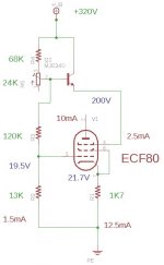
This is what I now plan to build, it based on the Morgan Jones circuit. The gate current of the MJ340 should be less than 2.5mA/50 or 0.0001mA or about 4V variation on g2. If I add a 0.33uf cap that should improve a bit. I am considering sharing the bias string between the two channels, which would mean halving the resistor vaues.
What does anyone think.
Shoog
Attachments
I have the same issue than the first post: voltages of g2 higher than anode.
The problem is that we don't know the characteristics of the pentode at a lower g2 than specified for under 100V. For this reason we are tempted to use it at higher voltages but it seems unorthodox and maybe destructive.
I thought of using the G3o pentode instead, which has specifications for g2 of 60V.
Any idea anyone?
- Status
- This old topic is closed. If you want to reopen this topic, contact a moderator using the "Report Post" button.
- Home
- Amplifiers
- Tubes / Valves
- PCF80 -Designing a Pentode Constant Current Sink - help needed.