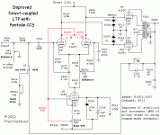
Any idea anyone?
Use a solid state CCS instead . Much more convienient and cheaper
316a
I LM337 will have fairly low performance since its impedance drops with increasing frequency. A pentode will overcome this - but at the cost of requiring a lot of voltage. The arrangement i arrived at in an earlier post has worked well for me.
However you will get considerably better performance at much less complexity from a discrete SS CCS which can be as simple as a cascoded pair of IX10M45 chips. Even a single IX10M45 will probably match the pentode. Better performance will equal better sound regardless of whether it is SS or valve based.
Shoog
Hi Shoog, I am glad you still responded years after and found a solution to your circuits.
I might follow your advice and use a couple of transistors to make another CCS for the next stage of the amplifier. As for the input stage I prefer using the pentode c3 because the G2 voltages are specified at 60V.
Seriously has anyone come with any testing of pentodes with G2 greater than the anode voltage? I am very curious about this.
I found the answer on this website : Electrons in Screened Grids and Pentodes
The suppressor grid g3 prevents the current of g2 from increasing with secondary emission of electrons as its voltage becomes greater than the anode voltage and acting as a second anode.
That finding confirms many designs that I saw using g2 voltages way over anode.
This also confirms the curves and the safety of using pentodes voltages with g2>anode in CCS for balanced operation as the voltage will stay constant at the anode and will not drop further.
There is one little problem with the pentode ccs: the input grids of the differential pair are at +120V and may require a capacitor in serie with the feedback signal to prevent that voltage to reach the speakers/out transformer secondaries.
I am welcoming any suggestions on design of feedback:
Just for thoughts see attachment
I am welcoming any suggestions on design of feedback:
Just for thoughts see attachment
Attachments
I finished this project a year ago now!
It is quite complex... the amp has 3 heather bias... a modified LTP sitting over a pentode current sink with a dedicated -150V supply and heather supply...
ECC99 LTP at 400V+ + LTP drawing 30 mA of current is not very efficient
but who cares for driving a pair of KT150 p-p at 150mA 600V
It is quite complex... the amp has 3 heather bias... a modified LTP sitting over a pentode current sink with a dedicated -150V supply and heather supply...
ECC99 LTP at 400V+ + LTP drawing 30 mA of current is not very efficient
but who cares for driving a pair of KT150 p-p at 150mA 600V
- Status
- This old topic is closed. If you want to reopen this topic, contact a moderator using the "Report Post" button.
- Home
- Amplifiers
- Tubes / Valves
- PCF80 -Designing a Pentode Constant Current Sink - help needed.
